Rule 420-3-16-AI
Ala. Admin. Code r. 420-3-16-AI
Appendix I - Pasteurization Equipment and Controls - Tests
Effective Dec 2, 2018Repealed and New Rule: Filed October 18, 2018; effective December 2, 2018.Alabama Department of Public Health
I. TESTING APPARATUS SPECIFICATIONS TEST THERMOMETER
1. Mercury or Non-toxic Liquid-in-Glass-Actuated: Readily cleanable; plain front; enameled back; length at least 30.5 centimeters (12 inches); immersion point to be etched on stem and mercury or non-toxic liquid to stand in contraction chamber at 0°C (32°F). Non-toxic liquid-in-glass-actuated thermometers shall have accuracy and reliability equivalent to mercury thermometers.
Scale Range: At least 7°C (12°F) below and 7°C (12°F) above the pasteurization temperature at which the operating thermometer is used, with extensions of the scale on either side permitted and protected against damage at 149°C (300°F).
Temperature Represented by Smallest Scale Division: 0.1°C (0.2°F).
Number of Degrees per 25 Millimeters (1 inch) of Scale: Not more than 4°C or not more than 6°F.
Accuracy: Within ± 0.1°C (± 0.2°F), throughout specified scale range. The accuracy shall be checked against a thermometer which has been tested by or is traceable to NIST.
Bulb: Corning normal or equally suitable thermometric glass.
Case: Suitable to provide protection during transit and periods when not in use.
2. Digital Test Thermometer: Hand-held; high accuracy digital thermometer; and battery or AC line powered. Calibration is protected from unauthorized changes.
Range: -18°C to 149°C (0ºF to 300°F); temperature represented by smallest scale division, 0.01°C or ºF and digital display.
Accuracy: System accuracy of: ± 0.056°C (± 0.100°F); Probe accuracy of: ± 0.05°C (± 0.09°F); repeatability of ± 0.005°C (± 0.009°F); three (3) month stability: ± 0.025°C (± 0.045°F). Thermometer accuracy from 0°C to 150°C (32ºF to 302°F): ± 0.05°C (± 0.09°F). Calibration uncertainty: ± 0.0047°C (± 0.00846°F). The accuracy shall be checked against a thermometer which has been tested by or is traceable to NIST. This calibration shall be performed annually by a properly trained representative of an “Official Laboratory” or an “Officially Designated Laboratory”; or by a qualified representative of a thermometer manufacturer; or by a properly trained Health Officer. The calibration protocol/SOP shall be developed by the Health Officer in cooperation with the thermometer manufacturer and FDA. Documentation of the identity of the properly trained Health Officer shall be maintained by the Health Officer. A signed certificate of calibration for the digital thermometer shall be maintained with the unit.
Self-Diagnostic Circuitry: Circuitry shall provide constant monitoring of all sensing, input, and conditioning circuits. The diagnostic circuitry should be capable of identifying the probe and its calibration information. Without a correct connection of the probe, the display shall alert the operator and no temperature will be displayed.
Electro-magnetic Compatibility: Shall be documented for these devices for their intended use and available to the Health Officer. Units to be used in the “field” shall have been tested for heavy industrial standards, as specified in the European Electromagnetic Compatibility Directive.
Immersion: Minimum immersion point shall be marked on the probe. During control tests, the probes shall be immersed to equal depths in a water or oil bath.
Case: Suitable to provide protection during transit and periods when not in use.
GENERAL PURPOSE THERMOMETER
Type: Pocket type.
Scale Range: 1°C (30°F) to 100°C (212°F), with extensions of the scale on either side permitted. Protected against damage at 105°C (220°F).
Temperature Represented by Smallest Scale Division: 1°C (2°F).
Accuracy: Within ± 1°C (± 2°F), throughout the specified scale range. Checked periodically against a known accurate thermometer.
In the case of mercury actuated general-purpose thermometers, the following additional specifications shall apply:
Magnification of Mercury Column: To apparent width of not less than 1.6 millimeter (0.0625 of an inch).
Number of Degrees per Inch of Scale: Not more than 29°C or not more than 52°F.
Case: Metal, provided with a fountain pen clip.
Bulb: Corning normal or equally suitable thermometric glass.
ELECTRICAL CONDUCTIVITY MEASURING DEVICES
Type: Manual or automatic.
Conductivity: Capable of detecting change produced by the addition of ten (10) ppm of sodium chloride, in water of 100 ppm of hardness.
Electrodes: Standard.
Automatic Instruments: Electric clock, time divisions not over 0.2 of a second.
TIME MEASURING DEVICE
An accurate time measuring device may include but is not limited to a stopwatch, digital watch, conductivity device timer, and any other device which keeps time accurately.
STOPWATCH
Type: Open face, indicating fractional seconds.
Accuracy: Accurate to 0.2 of a second.
Hands: Sweep hand, if applicable, one complete turn every sixty (60) seconds or less.
Scale: Divisions of not over 0.2 of a second.
Crown: Depression of crown or push button starts, stops, and resets to zero.
Type:
II. TEST PROCEDURES
- 1. Test thermometer meeting the specifications cited in Section I of this appendix.
- 2. Water, oil or other suitable media bath and agitator.
3. Suitable means of heating the media bath.
Method: Both the indicating and/or airspace thermometer, if applicable, and test thermometer shall be exposed to water, oil, or other suitable media of a uniform temperature. The indicating thermometer and/or airspace thermometer, if applicable, reading is compared to the reading of the test thermometer.
Procedure:
- 1. Prepare a media bath by raising the temperature of the media to within 2°C (3°F) of the lowest sealed cut-out pasteurization or ultra-pasteurization temperature or minimum legal indicating or airspace temperature for batch pasteurization.
- 2. Stabilize the media bath temperature and agitate rapidly.
- 3. Continue agitation and insert the indicating and/or airspace thermometer, if applicable, and test thermometer to the indicated immersion point.
- 4. Compare the thermometer readings at a temperature within the test range.
- 5. Repeat the comparison of the thermometer readings.
- 6. If the results of this test are outside the Criteria noted above, the indicating thermometer or airspace thermometer, if applicable, shall be adjusted by milk plant personnel to agree with the test thermometer, retest and record the action taken on the appropriate form.
- 7. When compliance is achieved and/or verified, record the thermometer readings from both comparisons and record the thermometer identification or location on the appropriate form.
8. Re-seal as appropriate the sensing elements and control boxes of the digital thermometers.
Action: If the pasteurization or ultra-pasteurization system fails this test, the pasteurization or ultra-pasteurization system shall not be allowed to operate until the cause of this failure has been corrected and compliance has been verified by the Health Officer; or in the case of HACCP listed milk plants, qualified industry personnel, acceptable to the Health Officer, in compliance with Rule 420-3-16-.10(21-22) or on an emergency basis, an industry temporary testing and sealing program authorized by the Health Officer in compliance with Rule 420-3-16-.10(21-22).
TEST 2
TEMPERATURE RECORDING AND RECORDER-CONTROLLER
THERMOMETERS - TEMPERATURE ACCURACYReference: Rule 420-3-16-.10(17-18) and Rule 420-3-16-.10(21-22)
Application: To all temperature recording and recorder-controller thermometers used to record milk and/or milk product temperatures during pasteurization and/or ultra-pasteurization, except those which are electronic or computer controlled.
Frequency: Upon installation; at least once each three (3) months thereafter; whenever the sensing element has been repaired and/or replaced; or whenever the regulatory seal has been broken.
Criteria: Within ± 0.5°C (± 1°F), in a specified scale range as described in Procedure 1 below; provided, that on a batch pasteurizer used solely for thirty (30) minute pasteurization of milk and/or milk products at temperatures above 71°C (160°F), the temperature recording thermometer shall be accurate to within ± 1°C (± 2°F) between 71°C (160°F) and 77°C (170°F).
Apparatus:
- 1. The indicating thermometer which was previously tested against a known accurate test thermometer.
- 2. Water, oil, or other suitable media bath and agitator.
- 3. Suitable means of heating the media bath.
4. Ice.
Note: When this test is performed on temperature recorder-controllers used with HHST pasteurization systems that operate at or above the boiling point of water, an oil or other suitable media bath shall be substituted for the processing (operating) temperature water mentioned in Procedures 1, 4, 5, 6, and 7 as well as the boiling water mentioned in Procedures 2, 3 and 5. The temperature of the oil bath that is used in place of the boiling water shall be above the normal operating range but below the highest temperature division on the chart.
Method: The testing of a temperature recording or recorder-controller thermometer for temperature accuracy involves the determination of whether or not the temperature pen-arm will return to within ± 0.5ºC (± 1ºF) or ± 1°C (± 2°F) as provided for in the Criteria above, of its previous setting, after exposure to high heat and melting ice.
Procedure:
1. Heat a media bath to a constant temperature utilizing one (1) of the following temperatures:
- a. Lowest sealed cut-out pasteurization temperature; or
b. Minimum legal indicating or airspace pasteurization temperature for batch pasteurization; provided, that on a batch pasteurizer used solely for thirty (30) minute pasteurization of milk and/or milk products at temperatures above 71°C (160°F), this test shall be conducted with a media bath temperature above 71°C (160°F) and below 77°C (170°F).
Immerse the temperature recording or recorder-controller thermometer sensing element into the media bath. After a stabilization period of five (5) minutes, if necessary adjust the temperature re-cording or recorder-controller thermometer pen to read exactly as the previously tested indicating thermometer. The media bath shall be rapidly agitated throughout this stabilization period.
- 2. Prepare a second media bath by heating the media bath to the boiling point of water, or in the case of HHST pasteurization systems, to a temperature above the normal operating range but below the highest temperature division on the chart, and maintain temperature. Prepare a third media bath with ice and water. Place all media baths within working distance of the temperature recording or recorder-controller thermometer temperature-sensing element(s).
- 3. Immerse the temperature recording or recorder-controller thermometer sensing element into the hotmedia bath as prepared in Procedure 2, above, for not less than five (5) minutes.
- 4. Remove the temperature recording or recorder-controller thermometer sensing element from the hot media bath and immerse it in the media bath as prepared in Procedure 1 above. Allow a five (5) minute stabilization period for both the indicating and temperature recording or recorder-controller thermometers. Compare the readings of the indicating and temperature recording or recorder-controller thermometers. The temperature recording or recorder-controller thermometer reading shall be within ± 0.5ºC (± 1ºF) or ± 1°C (± 2°F) as provided for in the Criteria above, of the indicating thermometer reading.
- 5. Remove the temperature recording or recorder-controller thermometer sensing element from the media bath in the temperature range for the process being used and immerse it in the ice and water bath for not less than five (5) minutes.
- 6. Remove the temperature recording or recorder-controller thermometer sensing element from the ice and water bath and immerse it in the media bath as prepared in Procedure 1 above. Allow a five (5) minute stabilization period for both the indicating and temperature recording or recorder-controller thermometers. Compare the readings of the indicating and temperature recording or recorder-controller thermometers. The temperature recording or recorder-controller thermometer reading shall be within ± 0.5°C (± 1°F) or ± 1°C (± 2°F) as provided for in the Criteria above, of the indicating thermometer reading.
7. When compliance is achieved and/or verified, re-seal the thermometer sensing elements and recorder-controller as necessary and record the indicating and temperature recording thermometer or recorder-controller thermometer readings obtained from Procedures 1, 4, and 6 above on the appropriate form.
Action: If the temperature recording or recorder-controller thermometer pen does not return to ± 0.5°C (± 1°F) or ± 1°C (± 2°F) as provided in Procedures 4 and 6 above, the temperature recording or recorder-controller thermometer shall be repaired or replaced by milk plant personnel. If the pasteurization or ultra-pasteurization system fails this test, the pasteurization or ultra-pasteurization system shall not be allowed to operate until the cause of this failure has been corrected and compliance has been verified by the Health Officer; or in the case of HACCP listed milk plants, qualified industry personnel acceptable to the Health Officer in compliance with Rule 420-3-16-.10(21-22); or on an emergency basis, an industry temporary testing and sealing program authorized by the Health Officer in compliance with Rule 420-3-16-.10(21-22).
TEST 3
TEMPERATURE RECORDING AND RECORDER-CONTROLLER
THERMOMETERS - TIME ACCURACYReference: Rule 420-3-16-.10(17-18) and Rule 420-3-16-.10(21-22)
Application: To all temperature recording and recorder-controller thermometers used to record the time of pasteurization and/or ultra-pasteurization.
Frequency: Upon installation; at least once each three (3) months thereafter; whenever the temperature recorder-controller thermometer or programmable recording thermometer has been repaired and/or replaced; or whenever the regulatory seal on a temperature recorder-controller thermometer or programmable recording thermometer or sensing element has been broken.
Criteria: The recorded time of pasteurization or ultra-pasteurization shall not exceed the true elapsed time.
Apparatus: An accurate time measuring device.
Method: A comparison of the recorded time over a period of not less than thirty (30) minutes with an accurate time measuring device.
Procedure:
- 1. Determine if the recording chart is appropriate for the temperature recording or recorder-controller thermometer. Ensure that the recording chart pen is aligned with the time arc of the recording chart at both the center and the outside edge.
- 2. Inscribe a reference mark at the pen point on the recording chart and record the time.
- 3. At the end of thirty (30) minutes utilizing an accurate time measuring device, inscribe a second reference mark at the pen point position on the recording chart.
- 4. Determine the distance between the two (2) reference marks and compare the distance with the time-scale divisions on the recording chart at the same temperature.
5. Re-seal the sensing elements and recorder-controller as necessary; enter the results on the recording chart and initial the recording chart; and record the beginning and ending times on the appropriate Form.
Action: If the recorded time is incorrect, the temperature recording or recorder-controller thermometer device shall be adjusted or repaired by milk plant personnel. If the pasteurization or ultra-pasteurization system fails this test, the pasteurization or ultra-pasteurization system shall not be allowed to operate until the cause of this failure has been corrected and compliance has been verified by the Health Officer; or in the case of HACCP listed milk plants, qualified industry personnel acceptable to the Health Officer in compliance with Rule 420-3-16-.10(21-22); or on an emergency basis, an industry temporary testing and sealing program authorized by the Health Officer in compliance with Rule 420-3-16-.10(21-22).
TEST 4
TEMPERATURE RECORDING AND RECORDER-CONTROLLER
THERMOMETERS - CHECKED AGAINST INDICATING THERMOMETERReference: Rule 420-3-16-.10(17-18) and Rule 420-3-16-.10(21-22)
Application: To all temperature recording and recorder-controller thermometers used to record milk and/or milk product temperatures during pasteurization or ultra-pasteurization, and for batch pasteurizer digital combination airspace/recording thermometers with a continuous recording of the airspace temperature and where the airspace temperature is read and recorded on the recording chart only at the start of the pasteurization holding period.
Frequency: Upon installation; at least once each three (3) months thereafter; whenever the temperature recording or recorder-controller thermometer has been repaired and/or replaced; whenever the regulatory seal has been broken; and daily and immediately after a recording chart has been changed by milk plant personnel.
Criteria: The temperature recording thermometer and recorder-controller thermometer shall not read higher than the indicating or airspace thermometer which were previously tested against a known accurate test thermometer.
Apparatus: No supplementary materials required.
Method: This test requires only that the reading of the temperature recording thermometer, recorder-controller thermometer, or airspace recording thermometer be compared with the indicating thermometer at a time when both are exposed to a stabilized temperature at or above the minimum legal pasteurization temperature.
Procedure:
- 1. When the indicating and temperature recording or recorder-controller thermometer temperature readings are stabilized at or above the minimum legal pasteurization temperature, read the indicating thermometer.
- 2. For batch pasteurizers, when the airspace indicating and recording temperature readings are stabilized at or above the minimum legal pasteurization temperature, read the airspace thermometer.
- 3. Immediately enter the results; the time at which this comparison was made; and initial the recording chart. This may be accomplished by inscribing a line intersecting the recorded temperature arc at the pen location or any other method acceptable to the Health Officer.
4. Record the observed indicating and temperature recording thermometer or recorder-controller thermometer readings on the appropriate form.
1. With the pasteurization system operating on water, place the FDD in the diverted-flow position.
- a. For single stem FDDs, disconnect the forward-flow sanitary piping and observe the valve seat for leakage. Check the leak escape ports to see if they are open; or
- b. For dual stem FDDs, observe the leak-detect line discharge or sight glass for leakage.
2. Record the results of the test on the appropriate form.
Action: If leakage is observed, suitable repairs shall be made to the FDD by milk plant personnel. If after adjustment and/or repair the FDD fails this test, the pasteurization system shall not be allowed to operate until the cause of this failure has been corrected and compliance has been verified by the Health Officer; or in the case of HACCP listed milk plants, qualified industry personnel acceptable to the Health Officer in compliance with Rules 420-3-16-.10(21-22); or on an emergency basis, an industry temporary testing and sealing program authorized by the Health Officer in compliance with Rules 420-3-16-.10(21-22).
5.2 OPERATION OF THE VALVE STEM(S)
Apparatus: Suitable tools for tightening the packing nut on the valve stem of a single stem FDD.
Method: Observe the valve stem(s) for ease of movement.
Procedure:
- 1. For single stem FDDs, tighten the valve stem packing nut as much as possible. Operate the pasteurization system at maximum operating pressure and place the FDD in both forward and diverted-flow several times. The valve stem shall move freely in both forward and diverted-flow positions when the stem-packing nut is fully tightened. Note the freedom of action of the valve stem.
- 2. For dual stem FDDs, operate the pasteurization system at maximum operating pressure and place the FDD in both forward and diverted-flow several times. The valve stems shall move freely in both forward and diverted-flow positions. Note the freedom of action of the valve stems.
3. Record the results of the test on the appropriate form.
Action: If the valve stem(s) action is sluggish, suitable adjustment or repair shall be made by milk plant personnel. If after adjustment and/ pasteurization system shall not be allowed to operate until the cause of this failure has been corrected and compliance has been verified by the Health Officer; or in the case of HACCP listed milk plants, qualified industry personnel acceptable to the Health Officer in compliance with Rule 420-3-16-.10(21-22); or on an emergency basis, an industry temporary testing and sealing program authorized by the Health Officer in compliance with Rule 420-3-16-.10(21-22).
5.3 DEVICE ASSEMBLY - SINGLE STEM FDD
Apparatus: Suitable tools for the disassembly of the FDD and any connected sanitary piping.
Method: When the FDD is improperly assembled and in diverted-flow, below the cut-out temperature, observe the function of the timing pump and all other flow-promoting devices capable of causing flow through the FDD.
Procedure:
- 1. With the pasteurization system in operation, in “Process” mode, and below the cut-in temperature, unscrew by one-half (1/2) turn, the 13H hex nut that holds the top of the valve to the valve body. This shall de-energize the timing pump and all other flow-promoting devices which are capable of causing flow through the FDD. In addition, separators and/or downstream vacuum sources shall be effectively valved-out of the pasteurization system. This test shall be conducted without any sanitary piping connected to the forward-flow port of the FDD. This allows for the movement of the top of the valve when the hex nut is loosened. Re-tighten the 13H hex nut.
- 2. With the pasteurization system in operation, in “Process” mode, and below the cut-in temperature, remove the connecting key which is located at the base of the valve stem. The timing pump and all other flow-promoting devices which are capable of causing flow through the FDD shall be de-energized. In addition, separators and/or downstream vacuum sources shall be effectively valved-out of the pasteurization system.
- 3. Attempt to restart each flow-promoting device capable of causing flow through the FDD. None of these flow-promoting devices shall start or operate. Separators and/or downstream vacuum sources shall remain effectively valved-out of the pasteurization system.
4. Record the results of the test on the appropriate form.
Action: If any flow-promoting device fails to respond as indicated above, an immediate check of the FDD assembly and wiring is required by milk plant personnel to locate and correct the cause of the failure. If after adjustment and/or repair the FDD fails this test, the pasteurization system shall not be allowed to operate until the cause of this failure has been corrected and compliance has been verified by the Health Officer; or in the case of HACCP listed milk plants, qualified industry personnel acceptable to the Health Officer in compliance with Rule 420-3-16-.10(21-22); or on an emergency basis, an industry temporary testing and sealing program authorized by the Health Officer in compliance with Rule 420-3-16-.10(21-22).
5.4 DEVICE ASSEMBLY - DUAL STEM DEVICE
Note: the test procedure presented in this section is typical of tests accepted by FDA for various specific types of FDDs. Testing details, which may vary, are provided in individual FDD operator’s manuals that have been reviewed by the FDA and are specified by part number in FDA’s M-bs. In each of these M-b accepted test methods, if the words "metering pump" or "timing pump" are used they shall be understood to mean "timing pump and all other flow-promoting devices, which are capable of causing flow through the FDD.”
Apparatus: No supplementary materials required.
Method: Observe the function of the timing pump and all other flow-promoting devices which are capable of causing flow through the FDD when the FDD is improperly assembled.
Procedure:
- 1. With the FDD in diverted-flow caused by temperature, and the FDD is properly assembled, move the FDD to the forward-flow position by moving the switch to the “Inspect” mode and disconnect the valve stem from the actuator of the valve being tested.
- 2. Move the FDD to the diverted-flow position by moving the switch to the “Product” mode and turn on the timing pump and all other flow-promoting devices which are capable of causing flow through the FDD. The timing pump and all other flow-promoting devices shall be de- energized and shall not run. If any flow-promoting device which is capable of causing flow through the FDD starts momentarily and then stops running, it may indicate the improper wiring of the one (1) second time delay as allowed for in 16p.(B)2.b.(10). In addition, separators and/or downstream vacuum sources shall remain effectively valved-out of the pasteurization system. Move the switch to the “Inspect” mode and properly reassemble the FDD. Start the timing pump and all other flow-promoting devices which are capable of causing flow through the FDD to determine if the FDD has been properly reassembled.
- 3. Repeat this procedure for the other actuator.
4. Record the results of the test on the appropriate form.
Action: If any of the flow-promoting devices which are capable of causing flow through the FDD fail to respond as indicated, an immediate check of the FDD assembly and wiring shall be conducted by milk plant personnel to locate and correct the problem. If after adjustment and/or repair the FDD fails this test, the pasteurization system shall not be allowed to operate until the cause of this failure has been corrected and compliance has been verified by the Health Officer; or in the case of HACCP listed milk plants, qualified industry personnel acceptable to the Health Officer in compliance with Rule 420-3-16-.10(21-22); or on an emergency basis, an industry temporary testing and sealing program authorized by the Health Officer in compliance with Rule 420-3-16-.10(21-22).
5.5 MANUAL DIVERSION
Apparatus: No supplementary materials required.
Method: Observe that the appropriate responses in Procedures 1 and 2, as required below, have occurred during the activation and deactivation of manual diversion.
Procedure:
1. With the HTST pasteurization system in operation and the FDD in the forward-flow position, activate the manual divert control.
- a. The FDD shall assume the diverted-flow position.
- b. Any flow-promoting device downstream from the FDD, which is capable of causing flow through the FDD shall be de-energized.
- c. Any separator and/or vacuum source downstream from the FDD shall be effectively valved-out.
2. If a booster pump is installed in the HTST pasteurization system and the pasteurization system is in operation with the FDD in the forward-flow position:
- a. Activate the manual divert control. The booster pump shall be de-energized. The required minimum pressure differential of at least 6.9 kPa (1 psi) between raw milk and/or milk product and pasteurized milk and/or milk product in the regenerator shall be maintained.
b. After the raw pressure reaches zero (0) psi, deactivate the manual divert control and observe that the required minimum pressure differential of at least 6.9 kPa (1 psi) between raw milk and/or milk product and pasteurized milk and/or milk product in the regenerator has been maintained.
Action: If the above described required actions do not occur, or the required pressure differential between raw and pasteurized milk and/or milk product is not maintained, the HTST pasteurization system shall be immediately reviewed and evaluated by milk plant personnel and the indicated deficiencies corrected or proper adjustments made. If after adjustment and/or repair the FDD fails this test, the pasteurization system shall not be allowed to operate until the cause of this failure has been corrected and compliance has been verified by the Health Officer; or in the case of HACCP listed milk plants, qualified industry personnel acceptable to the Health Officer in compliance with Rule 420-3-16-.10(21-22); or on an emergency basis, an industry temporary testing and sealing program authorized by the Health Officer in compliance with Rule 420-3-16-.10(21-22).
5.6 RESPONSE TIME
Apparatus:
- 1. Water, oil or other suitable media bath and agitator.
- 2. Suitable means of heating the media bath.
3. An accurate time measuring device.
Method: Determine that the elapsed time does not exceed one (1) second between the instant of the activation of the FDD control mechanism at cut-out temperature, on declining temperature, and the instant the FDD takes the fully diverted-flow position.
Procedure:
- 1. With the water, oil, or suitable media bath at a temperature above cut-out temperature, allow the water, oil, or other suitable media to cool gradually. The moment the cut-out mechanism is activated, start the accurate time measuring device. The moment the FDD takes the fully-diverted position, stop the accurate time measuring device.
2. Record the results of the test on the appropriate form.
Action: If the response time exceeds one (1) second, immediate action shall be taken by milk plant personnel to correct this FDD deficiency. If after adjustment and/or repair the FDD fails this test, the pasteurization system shall not be allowed to operate until the cause of this failure has been corrected and compliance has been verified by the Health Officer; or in the case of HACCP listed milk plants, qualified industry personnel acceptable to the Health Officer in compliance with Rule 420-3-16-.10(21-22); or on an emergency basis, an industry temporary testing and sealing program authorized by the Health Officer in compliance with Rule 420-3-16-.10(21-22).
5.7 TIME DELAY INTERLOCK WITH TIMING PUMP AND OTHER FLOW PROMOTING DEVICES
Application: To all dual stem FDDs with a manual forward-flow control switch.
Apparatus: No supplementary materials required.
Method: Determine that the FDD does not assume a manually induced forward-flow position while the timing pump or any other flow-promoting device which is capable of causing flow through the FDD is operating.
Procedure: With the pasteurization system operating in forward-flow, move the control switch to the "Inspect" position and observe that the following events automatically occur in sequence:
- 1. The FDD immediately moves to the diverted-flow position and the timing pump and all other flow-promoting devices, which are capable of causing flow through the FDD, are de-energized, or in the case of separators and/or downstream vacuum sources, are effectively valved-out of the pasteurization system.
- 2. The FDD remains in the diverted-flow position until the timing pump and all other flow-promoting devices which are capable of causing flow through the FDD have completely stopped running or in the case of a separator and/or downstream vacuum sources, are effectively valved-out of the pasteurization system.
- 3. Then the FDD shall assume the forward-flow position.
4. Record the results of the test on the appropriate form and seal the control enclosure.
Action: If the above sequence of events do not occur, either a timer adjustment or wiring change is required to be made by pasteurization plant personnel. If after adjustment and/or repair the FDD fails this test, the pasteurization system shall not be allowed to operate until the cause of this failure has been corrected and compliance has been verified by the Health Officer; or in the case of HACCP listed milk plants, qualified industry personnel acceptable to the Health Officer in compliance with Rule 420-3-16-.10(21-22); or on an emergency basis, an industry temporary testing and sealing program authorized by the Health Officer in compliance with Rule 420-3-16-.10(21-22).
5.8 CIP TIME DELAY RELAY
Application: To all continuous-flow pasteurization systems in which it is desired to run any flow-promoting devices during the CIP cycle.
Criteria: When the mode switch on the FDD is moved from “Process” to “CIP,” the FDD shall move immediately to the diverted-flow position. It shall remain in the diverted-flow position for at least ten (10) minutes, with all public health controls required in the “Process” mode functioning, before starting its normal cycling in the “CIP” mode. In HTST pasteurization systems, the booster pump shall be de-energized, separators between raw regenerator sections and separators and/or vacuum sources downstream of the FDD shall be effectively valved-out of the pasteurization system during the required ten (10) minute time delay.
Apparatus: An accurate time measuring device.
Method: Determine that the set point on the “CIP” time delay is equal to or greater than the required ten (10) minutes by observing the time when the FDD moves to the forward-flow position or is again capable of moving to the forward-flow position.
Procedure:
1. Operate the pasteurization system in forward-flow, with the mode switch on the FDD controls in the “Process” position, using water above the minimum legal pasteurization temperature. For magnetic flow meter based timing systems, operate the system at a flow-rate below the flow alarm set point and above the low-flow or loss-of-signal alarm set point.
Note: The appropriate temperature sensing elements may be placed in a water, oil, or other suitable media bath to simulate the normal pasteurization temperature within the holding tube as an alternative to heating the water in the pasteurization system above the minimum legal pasteurization temperature.
- 2. Move the mode switch on the FDD control to the “CIP” position. The FDD shall move immediately to the diverted-flow position. Start the accurate time measuring device when the FDD moves to the diverted-flow position. Confirm that all public health controls required in diverted flow in the “Process” mode are functioning.
- 3. Stop the accurate time measuring device when the FDD moves to the forward-flow position or is again capable of moving to the forward-flow position. At this time, the pasteurization system may be operated without the FDD controls normally required during the “Process” mode during product processing.
- 4. Record the results of the test on the appropriate form.
5. Re-seal the regulatory enclosure over the time delay.
Action: If the FDD does not remain in the diverted-flow position for at least the required ten (10) minutes after the FDD mode switch is moved from “Process” to “CIP,” increase the set point on the time delay and repeat this test procedure. All public health controls required when the pasteurization system is in “Process” mode and in diverted-flow shall be functional during this required ten (10) minutes. If the above does not occur, either a timer adjustment or wiring change is required to be made by milk plant personnel. If after adjustment and/or repair the FDD fails this test, the pasteurization system shall not be allowed to operate until the cause of this failure has been corrected and compliance has been verified by the Health Officer; or in the case of HACCP listed milk plants, qualified industry personnel acceptable to the Health Officer in compliance with Rule 420-3-16-.10(21-22); or on an emergency basis, an industry temporary testing and sealing program authorized by the Health Officer in compliance with Rule 420-3-16-.10(21-22).
5.9 LEAK-DETECT VALVE FLUSH - TIME DELAY
Application: To HTST continuous-flow pasteurization systems in which the space between the divert and leak-detect valves is not self-draining when the FDD is in the diverted-flow position.
Criteria: The space between the divert and leak-detect valves shall be flushed for at least one (1) second and not more than five (5) seconds after the divert valve moves to the forward-flow position and before the leak-detect valve moves to the forward-flow position.
The maximum of five (5) seconds delay is not applicable if:
- 1. The minimum acceptable pasteurization holding time in diverted-flow can be achieved without the use of any restriction in the divert line; or
2. The timing system is magnetic flow meter based.
Apparatus: An accurate time measuring device.
Method: Observe the movement of the divert and leak-detect valves to the forward-flow position and measure the time interval between the movement of the two (2) valves.
Procedure:
1. Move the FDD from the diverted-flow position to the forward-flow position either by:
a. Raising the temperature above the cut-in set point; or
Note: The appropriate temperature sensing elements may be placed in a water, oil, or other suitable media bath to simulate the normal pasteurization temperature within the holding tube as an alternative to heating the water in the pasteurization system above the minimum legal pasteurization temperature.
- b. Operating the HTST pasteurization system above the cut-in temperature in manual divert mode and then deactivate the manual divert control.
- 2. When the divert valve begins to move to the forward-flow position, start the accurate time measuring device.
- 3. When the leak-detect valve begins to move to the forward-flow position, stop the accurate time measuring device.
- 4. Record the elapsed time on the appropriate form.
5. If the elapsed time is at or above one (1) second and at or below five (5) seconds, except as noted in the exceptions in the Criteria above, seal the time delay as required.
Action: If the elapsed time is less than one (1) second or greater than five (5) seconds, except as noted in the exceptions in the Criteria above, appropriate changes to the pasteurization system or pasteurization system’s FDD controls shall be made by milk plant personnel. If after adjustment and/or repair the FDD fails this test, the pasteurization system shall not be allowed to operate until the cause of this failure has been corrected and compliance has been verified by the Health Officer; or in the case of HACCP listed milk plants, qualified industry personnel acceptable to the Health Officer in compliance with Rule 420-3-16-.10(21-22); or on an emergency basis, an industry temporary testing and sealing program authorized by the Health Officer in compliance with Rule 420-3-16-.10(21-22).
TEST 6
BATCH (VAT) PASTEURIZER LEAK-PROTECTOR OUTLET VALVE
Reference: Rule 420-3-16-.10(17) and Rule 420-3-16-.10(21-22)
Application: To all batch (vat) pasteurizers that have an outlet valve.
Frequency: Upon installation; and at least once each three (3) months thereafter.
Criteria: No leakage past the outlet valve seat in the closed position.
Apparatus: No supplementary materials required.
Method: By observing whether or not leakage past the outlet valve seat occurs when pressure is exerted against the upstream face of the outlet valve.
Procedure:
Action: If the temperature recording thermometer or recorder-controller thermometer reads higher than the indicating thermometer, the pen or temperature adjusting mechanism shall be adjusted by milk plant personnel to agree with the indicating thermometer. If after adjustment the temperature recording thermometer or recorder-controller thermometer fails this test, the pasteurization or ultra-pasteurization system shall not be allowed to operate until the cause of this failure has been corrected and compliance has been verified by the Health Officer; or in the case of HACCP listed milk plants, qualified industry personnel acceptable to the Health Officer in compliance with Rule 420-3-16-.10(21-22), or on an emergency basis, an industry temporary testing and sealing program authorized by the Health Officer in compliance with Rule 420-3-16-.10(21-22).
TEST 5
FDD - PROPER ASSEMBLY AND FUNCTION
Reference: Rule 420-3-16-.10(18); Rule 420-3-16-.10(21-22)
Application: 5.1 to 5.4 and 5.6 to 5.8 below apply to all FDDs used with continuous-flow pasteurization systems. 5.5 and 5.9 below apply only to FDDs used with HTST pasteurization systems.
Frequency: Upon installation; at least once each three (3) months thereafter; whenever the FDD has been repaired and/or replaced; or whenever the regulatory seal(s) has been broken.
Criteria: The FDD shall function as required in all operating situations and shall de-energize the timing pump and all other flow-promoting devices capable of causing flow through the FDD, in the event of a FDD malfunction or when the FDD is incorrectly assembled.
5.1 LEAKAGE PAST THE VALVE SEAT(S)
Apparatus: Suitable tools for the disassembly of the FDD and any connected sanitary piping.
Method: Observe the valve seat(s) for leakage.
Procedure:
- 1. Utilizing milk, milk products, or water, fill the batch (vat) pasteurizer to the normal operation level.
- 2. Observe the outlet valve in the closed position and determine whether or not milk, milk product, or water, respectively, is leaking past the outlet valve seat into the valve outlet.
3. Record the results of the test on the appropriate form.
Action: If leakage past the outlet valve seat occurs in the closed position, the outlet valve plug shall be repaired or replaced by milk plant personnel. If the outlet valve fails this test, the batch (vat) pasteurizer shall not be allowed to operate until the cause of this failure has been corrected and compliance has been verified by the Health Officer; or in the case of HACCP listed milk plants, qualified industry personnel acceptable to the Hea
420-3-16-.10(21-22); or on an emergency basis, an industry temporary testing and sealing program authorized by the Health Officer in compliance with Rules 420-3-16-.10(21-22).
TEST 7
INDICATING THERMOMETERS LOCATED WITHIN HTST PASTEURIZATION SYSTEMS - THERMOMETRIC RESPONSE
Reference: Rule 420-3-16-.10(18) and Rule 420-3-16-.10(21-22)
Application: To all HTST pasteurization systems, except for those in which the FDD is located downstream of the pasteurized regenerator section(s) and/or the final cooler section.
Frequency: Upon installation; at least once each three (3) months thereafter; whenever the indicating thermometer has been repaired and/or replaced; or whenever the regulatory seal on a digital sensing element or digital control box has been broken.
Criteria: Four (4) seconds or less.
Apparatus:
- 1. Accurate time measuring device.
- 2. The indicating thermometer, which was previously tested against a known accurate test thermometer.
- 3. Water, oil or other suitable media bath and agitator.
- 4. Suitable means of heating the media bath.
5. Ice and water media bath.
Method: The measuring of the time required for the reading of the indicating thermometer being tested to increase 7°C (12°F) through a specified temperature range. This temperature range shall include the minimum legal pasteurization temperature(s). If there are multiple cut-in temperatures and one (1) or more are separated by more than 7°C (12°F), this test shall also be conducted for any cut-in temperature(s) not included within the initial 7°C (12°F) range as addressed in Procedure 1 below.
Procedure:
- 1. Immerse the indicating thermometer in the media bath which has been heated to a temperature at least 11°C (19°F) higher than the minimum scale reading on the indicating thermometer. The media bath temperature shall be 4°C (7°F) higher than the highest pasteurization temperature set point (cut-in temperature) for which the indicating thermometer is being used.
2. Immerse the indicating thermometer in an ice and water media bath for several seconds to cool it.
Note: Continuous agitation of the heated media bath during the performance of Procedures 3, 4 and 5 is required. The elapsed time between the end of Procedure 1 and the beginning of Procedure 3 shall not exceed fifteen (15) seconds, unless a constant temperature media bath is used to prevent the heated media bath from cooling significantly.
- 3. Insert the indicating thermometer into the heated media bath to the proper indicating thermometer bulb immersion depth.
- 4. Start the accurate time measuring device when the indicating thermometer reads 11°C (19°F) below the heated media bath temperature.
- 5. Stop the accurate time measuring device when the indicating thermometer reads 4°C (7°F) below the heated media bath temperature.
6. Record the results of the test on the appropriate form.
For Example: For an indicating thermometer used at pasteurization temperature set points of 71.7°C (161°F) and 74.4°C (166°F), a media bath at a temperature of 78.3°C (173°F) could be used. 11°C (19°F) lower than a 78.3°C (173°F) media bath would be 67.8°C (154°F); 4°C (7°F) lower than a 78.3°C (173°F) media bath would be 74.4°C (166°F). Hence, after immersing the indicating thermometer that has been previously cooled in the ice and water media bath into the 78.3°C (173°F) bath, the accurate time measuring device is started when the thermometer reads 67.8°C (154°F) and the accurate time measuring device is stopped when it reads 74.3°C (166°F).
Note: The example included the pasteurization temperature set points of 71.7°C (161°F) and 74.4°C (166°F). If the pasteurization temperature set points had been 71.7°C (161°F) and 79.4°C (175°F), it would not have been possible to include both set points within a 7°C (12°F) span. With these set points of 71.7°C (161°F) and 79.4°C (175°F), the test would have to be conducted separately for each set point.
Action: If the response time exceeds four (4) seconds, the indicating thermometer shall be repaired or replaced by milk plant personnel. If the thermometer fails this test, the pasteurization system shall not be allowed to operate until the cause of this failure has been corrected and compliance has been verified by the Health Officer; or in the case of HACCP listed milk plants, qualified industry personnel acceptable to the Health Officer in compliance with Rule 420-3-16-.10(21-22); or on an emergency basis, an industry temporary testing and sealing program authorized by the Health Officer in compliance with Rule 420-3-16-.10(21-22).
TEST 8
TEMPERATURE RECORDER-CONTROLLER
THERMOMETERS - THERMOMETRIC RESPONSEReference: Rule 420-3-16-.10(18) and Rule 420-3-16-.10(21-22)
Application: To all HTST continuous-flow pasteurization systems, except for those in which the FDD is located downstream of the pasteurized regenerator section(s) and/or the final cooler section.
Frequency: Upon installation; at least once each three (3) months thereafter; whenever the temperature recorder-controller thermometer has been repaired and/or replaced; or whenever the regulatory seal has been broken.
Criteria: Five (5) seconds or less.
Apparatus:
- 1. Accurate time measuring device.
- 2. The indicating thermometer, which was previously tested against a known accurate test thermometer.
- 3. Water, oil or other suitable media bath and agitator.
4. Suitable means of heating the media bath.
Method: Measure the time interval between the instant when the temperature recorder-controller thermometer reads 7°C (12°F) below the cut-in temperature and the moment of cut-in by the temperature recorder-controller. This time interval measurement is made when the temperature recorder-controller sensing element is immersed in a rapidly agitated media bath maintained at 4°C (7°F) above the cut-in temperature.
Procedure:
- 1. Check and, if necessary, adjust the pen-arm setting of the temperature recorder-controller thermometer to read the same as the indicating thermometer at pasteurization temperature.
- 2. Allow the temperature recorder-controller sensing element to cool to room temperature.
- 3. Heat the media bath to 4°C (7°F) above the cut-in temperature while continuously agitating the media bath to ensure a uniform temperature.
- 4. Immerse the temperature recorder-controller sensing element in the media bath. Continue agitation during Procedures 5 and 6 below.
- 5. Start the accurate time measuring device when the temperature recorder-controller thermometer reaches a temperature of 7°C (12°F) below the cut-in temperature.
- 6. Stop the accurate time measuring device when the temperature recorder-controller cuts in.
- 7. Record the results of the test on the appropriate form.
8. Repeat Procedures 1 through 7 for each temperature cut-in set point.
- 1. A sanitary pressure gauge.
2. Pneumatic testing device, for checking and adjusting the pressure switch settings.
Note: A simple pneumatic testing device may be made from a sanitary tee with a cap on one outlet of the tee that is drilled and tapped and fitted in sequence from the cap with an air bleeder valve, an air pressure reducing valve (suggested range 0-60 psi), and a quick disconnect fitting for attaching a pneumatic device to a milk plant airline.
3. A test light of proper voltage placed in-series with the pressure switch contact and in parallel with the booster pump starter.
Method: Check and make the adjustment of the pressure switch to prevent the operation of the booster pump, unless the pressure of the pasteurized milk and/or milk product side of the regenerator section is greater by at least 6.9 kPa (1 psi) than any pressure that may be generated by the booster pump.
Procedure:
1. Determine the maximum pressure of the booster pump.
- a. Install the sanitary pressure gauge in a tee at the discharge of the booster pump.
- b. Operate the pasteurization system on water with the FDD in forward-flow, the timing pump operating at the minimum speed possible, and the booster pump operating at its maximum speed. If a separator and/or vacuum equipment is located between the raw outlet of the regenerator section and the timing pump, the separator and/or vacuum equipment shall be effectively valved-out of the pasteurization system.
- c. Determine the maximum pressure indicated by the pressure gauge under these conditions.
2. Check and set the pressure switch.
- a. Disconnect the pressure switch to be tested from the pasteurization system and connect it to one (1) of the outlets of the pneumatic testing device sanitary tee.
- b. Connect the sanitary pressure gauge to the third outlet of the sanitary tee.
c. Close the air pressure regulating valve and fully open the air bleeder valve. Slowly manipulate these valves to bring the air pressure in the pneumatic testing device within the desired range.
Note: By careful manipulation of the air pressure reducing valve and the air bleeder valve, the air pressure in the pneumatic testing device may be regulated slowly and precisely. When operating the pneumatic testing device, care shall be taken to avoid exposing the pressure switch and the sanitary pressure gauge to excessive pressure that might cause damage to the pressure switch.
- d. Remove the regulatory seal and cover to expose the adjustment mechanism on the pressure switch.
- e. Operate the pneumatic testing device and determine the pressure gauge reading at the booster pump start point on the pressure switch, which will light the test light. If the pressure switch is short circuited, the test light will be lit before the air pressure is applied.
- f. The booster pump start point shall be adjusted, if necessary, so as to occur at a pressure gauge reading at least 6.9 kPa (1 psi) greater than the maximum booster pump operating pressure, as determined under Step 1 of this Procedure. If an adjustment is necessary, refer to the manufacturer's instructions for the adjusting procedures. After adjustment, recheck the booster pump start point.
- g. Replace the cover, seal the pressure switch, and put the pressure switch sensing element back at its original location.
- 3. Identify the motor, casing, and impeller of the booster pump.
4. Record the maximum booster pump pressure, the pressure switch setting and the identity of the motor casing and impeller of the booster pump on the appropriate form.
Action: If the pressure switch fails this test, the pasteurization system shall not be allowed to operate until the cause of this failure has been corrected and compliance has been verified by the Health Officer; or in the case of HACCP listed milk plants, qualified industry personnel acceptable to the Health Officer in compliance with Rule 420-3-16-.10(21-22); or on an emergency basis, an industry temporary testing and sealing program authorized by the Health Officer in compliance with Rule 420-3-16-.10(21-22).
9.2 DIFFERENTIAL PRESSURE CONTROLLER
Application: Test 9.2.1 applies to all differential pressure controllers used to control the operation of booster pumps within HTST pasteurization systems or used to control the operation of FDDs on HHST and HTST pasteurization systems with the FDD located downstream of the pasteurized regenerator section(s) and/or the final cooler section.
Test 9.2.2 applies only to HTST pasteurization systems with the FDD located immediately following the holding tube.
Test 9.2.3 applies to the testing of continuous-flow pasteurization systems in which the differential pressure controller is used to control the operation of the FDD.
Frequency: Upon installation; at least once each three (3) months thereafter; whenever the differential pressure controller is adjusted or repaired; or whenever the regulatory seal has been broken.
Criteria: The booster pump shall not operate, or the pasteurization system shall not operate in forward-flow, unless the milk and/or milk product pressure in the pasteurized side of the regenerator section(s) is at least 6.9 kPa (1 psi) greater than the milk and/or milk product pressure in the raw side of the regenerator section(s). When the differential pressure controller is used to control the FDD on HHST pasteurization systems, and improper pressure occurs in the regenerator section(s), the FDD shall move to the diverted-flow position and remain in diverted-flow until the proper pressures are re-established in the regenerator section(s) and all milk and/or milk product-contact surfaces between the holding tube and the FDD have been held at or above the minimum legal pasteurization temperature continuously and simultaneously for at least the required time.
Apparatus:
- 1. A sanitary pressure gauge.
- 2. Pneumatic testing device described in Test 9.1 PRESSURE SWITCHES can be used for checking and adjusting the differential pressure switch setting.
- 3. Water, oil or other suitable media bath and agitator.
- 4. Suitable means of heating the media bath (refer to Test 9.2.2).
5. Test light (refer to Test 9.2.3).
Method: The differential pressure switch is checked and adjusted to prevent the operation of the booster pump, or prevent forward-flow, unless the milk and/or milk product pressure in the pasteurized side of the regenerator section(s) is at least 6.9 kPa (1 psi) greater than the pressure in the raw side of the regenerator section(s).
9.2.1 CALIBRATION OF THE DIFFERENTIAL PRESSURE CONTROLLER SENSING ELEMENTS
Procedure:
- 1. Loosen the sanitary pipeline connections to both differential pressure controller pressure sensing elements and wait for any liquid to drain through the loose sanitary pipeline connections. Both pointers or digital displays shall be within 3.5 kPa (0.5 psi) of 0 kPa (0 psi). If not, adjust the pointer(s) or the digital display(s) to read 0 kPa (0 psi).
- 2. Remove both differential pressure controller sensing elements from the pasteurization system and mount them on a testing tee which is connected either at the discharge of the booster pump or at the pneumatic testing device. Note the separation between the two (2) pointers or digital displays. A change in elevation of the differential pressure controller sensing elements may cause some change in the 0 kPa (0 psi) readings. Turn on the booster pump switch and activate the test switch/button to operate the booster pump, or if the pneumatic testing device is used in lieu of the booster pump, adjust the air pressure to the normal operating pressure of the booster pump. Note that the pointers or digital display reading separation is within 6.9 kPa (1 psi) of that observed before the pressure was applied.
3. Record the results of the test on the appropriate form.
Action: If the differential pressure controller fails to respond as indicated above, an immediate check of the differential pressure controller is required by milk plant personnel to correct the cause of the failure. If after adjustment and/or repair the differential pressure controller fails this test, the pasteurization system shall not be allowed to operate until the cause of this failure has been corrected and compliance has been verified by the Health Officer; or in the case of HACCP listed milk plants, qualified industry personnel acceptable to the Health Officer in compliance with Rules 420-3-16-.10(21-22); or on an emergency basis, an industry temporary testing and sealing program authorized by the Health Officer in compliance with Rules 420-3-16-.10(21-22).
9.2.2 HTST - INTERWIRING OF THE DIFFERENTIAL PRESSURE CONTROLLER WITH THE BOOSTER PUMP
Method: Determine if the booster pump stops running when the pressure differential is not properly maintained in the regenerator section(s).
Procedure:
1. Connect the pasteurized regenerator section differential pressure controller sensing element to a testing tee with the other end of the testing tee capped.
Note: If there is water in the HTST pasteurization system, ensure that the recorder-controller sensing element and the pasteurized regenerator section differential pressure controller sensing element ports are capped before the timing pump is turned on.
- 2. Turn on the timing pump and the booster pump.
- 3. Place the recorder-controller sensing element in a hot media bath which is above the cut-in temperature.
- 4. Increase the air supply on the testing tee to provide an adequate pressure differential to start the booster pump. The booster pump shall start running.
- 5. Decrease the air supply to the testing tee until the pasteurized milk and/or milk product differential pressure controller sensing element pressure is less than 14 kPa (2 psi) greater than the pressure on the raw milk and/or milk product side differential pressure controller sensing element. The booster pump shall stop running. Ensure that the FDD remains in the forward-flow position and the timing pump continues to operate.
6. Record the results of the test on the appropriate form.
Action: If the booster pump fails to stop running when the pressure differential is not maintained, milk plant personnel shall determine and correct the problem. If after adjustment and/or repair the differential pressure controller fails this test, the pasteurization system shall not be allowed to operate until the cause of this failure has been corrected and compliance has been verified by the Health Officer; or in the case of HACCP listed milk plants, qualified industry personnel acceptable to the Health Officer in compliance with Rule 420-3-16-.10(21-22); or on an emergency basis, an industry temporary testing and sealing program authorized by the Health Officer in compliance with Rule 420-3-16-.10(21-22).
9.2.3 INTERWIRING OF THE DIFFERENTIAL PRESSURE CONTROLLER WITH THE FDD IN AN HHST CONTINUOUS-FLOW PASTEURIZATION SYSTEM
Application: To all differential pressure controllers used to control the operation of FDDs on HHST continuous-flow pasteurization systems with the FDD located downstream of the pasteurized regenerator section(s) and/or final cooler section.
Method: The differential pressure controller is checked and adjusted to prevent forward-flow unless the milk and/or milk product pressure in the pasteurized side of the regenerator section(s) is at least 6.9 kPa (1 psi) greater than the pressure in the raw milk and/or milk product side of the regenerator section(s). In the case of milk and/or milk product-to-water-to-milk or milk product regenerators protected on the pasteurized side of the regenerator section(s), the “water side” of the regenerator section(s) shall be considered to be the "raw product side" for purposes of this test.
Procedure:
- 1. Wire the test light in series with the signal from the differential pressure controller to the FDD.
- 2. Calibrate the differential pressure controller and sensing elements. (Use Test 9.2.1.)
3. Adjust the pressure on the differential pressure controller sensing elements to their normal operating pressures, with the pasteurized milk and/or milk product pressure at least 14 kPa (2 psi) higher than the raw milk and/or milk product pressure.
- a. The test light shall be lit. If not, increase the pasteurized milk and/or milk product pressure or lower the raw milk and/or milk product pressure until the test light is lit.
- b. Gradually lower the pasteurized milk and/or milk product pressure or raise the raw milk and/or milk product pressure until the test light turns off.
- c. The test light shall turn off when the pasteurized milk and/or milk product pressure is at least 14 kPa (2 psi) higher than the raw milk and/or milk product pressure.
- d. Note the pressure differential at the point the test light turns off.
- e. Gradually raise the pasteurized milk and/or milk product pressure or lower the raw milk and/or milk product pressure until the test light turns on.
f. The test light shall not turn on until the pasteurized milk and/or milk product pressure is at least 14 kPa (2 psi) higher than the raw milk and/or milk product pressure. Note the pressure differential at the point the test light turns off.
Note: This test may be completed using a pneumatic testing device capable of producing pressure differentials on the sensing elements duplicating the conditions described above.
4. Record the results of the test on the appropriate forms.
Action: If the differential pressure controller fails to respond as indicated above, an immediate check of the differential pressure controller is required by milk plant personnel to locate and correct the problem. If after adjustment and/or repair the differential pressure controller fails this test, the pasteurization system shall not be allowed to operate until the cause of this failure has been corrected and compliance has been verified by the Health Officer; or in the case of HACCP listed milk plants, qualified industry personnel acceptable to the Health Officer in compliance with Rule 420-3-16-.10(21-22); or on an emergency basis, an industry temporary testing and sealing program authorized by the Health Officer in compliance with Rule 420-3-16-.10(21-22).
9.3 ADDITIONAL HTST PASTEURIZATION SYSTEM TESTS FOR BOOSTER PUMPS – INTERWIRING
Application: To all booster pumps used for HTST pasteurization systems where the FDD is located immediately downstream of the holding tube, except that Test 9.3.2 is not required to be performed on magnetic flow meter based timing systems.
Frequency: Upon installation; at least once each three (3) months thereafter; whenever there is any change to the booster pump or the booster pump interwiring; or when the regulatory seal has been broken.
Criteria: The booster pump shall be wired so it cannot operate if the FDD is in the diverted-flow position or if the timing pump is not in operation.
Apparatus:
- 1. A sanitary pressure gauge.
- 2. Pneumatic testing device, described in Test 9.1 Pressure Switches, can be used for checking and adjusting the differential pressure controller setting (refer to Test 9.1).
- 3. Water, oil or other suitable media bath and agitator.
4. Suitable means of heating the media bath.
9.3.1 BOOSTER PUMPS-INTERWIRED WITH FDD
Method: Determine if the booster pump stops running by dropping the temperature and causing the FDD to divert.
Procedure:
1. Connect the pasteurized regenerator section(s) differential pressure controller sensing element to a testing tee with the other end of the testing tee capped.
Note: If there is water in the HTST pasteurization system, ensure that the recorder-controller sensing element and the pasteurized regenerator section(s) differential pressure controller sensing element ports are capped before the timing pump is turned on.
- 2. Turn on the timing pump and the booster pump.
- 3. Place the recorder-controller sensing element in a hot media bath which is above the cut-in temperature.
- 4. Increase the air supply on the testing tee to provide an adequate pressure differential to start the booster pump. The booster pump shall start running.
- 5. Remove the recorder-controller sensing element from the hot media bath.
- 6. When the FDD moves to the diverted-flow position, the booster pump shall stop running. Ensure that the pressure differential remains greater than or equal to 6.9 kPa (1 psi) and the other flow-promoting devices which are capable of causing flow through the FDD in the timing system continue to operate.
7. Record the results of the test on the appropriate form.
Action: If the booster pump fails to stop running when the FDD is in the diverted-flow position, milk plant personnel shall determine and correct the cause. If after adjustment and/or repair the booster pump fails this test, the pasteurization system shall not be allowed to operate until the cause of this failure has been corrected and compliance has been verified by the Health Officer; or in the case of HACCP listed milk plants, qualified industry personnel acceptable to the Health Officer in compliance with Rule 420-3-16-.10(21-22) or on an emergency basis, an industry temporary testing and sealing program authorized by the Health Officer in compliance with Rule 420-3-16-.10(21-22).
9.3.2 BOOSTER PUMPS - INTERWIRED WITH THE TIMING PUMP
Method: Determine if the booster pump stops running when the timing pump is not running.
Procedure:
1. Connect the pasteurized regenerator section(s) differential pressure controller sensing element to a testing tee with the other end of the testing tee capped.
Note: If there is water in the HTST pasteurization system, ensure that the recorder-controller sensing element and the pasteurized regenerator section(s) differential pressure controller sensing element ports are capped before the timing pump is turned on.
- 2. Turn on the timing pump and the booster pump.
- 3. Place the recorder-controller sensing element in a hot media bath which is above the cut-in temperature.
- 4. Increase the air supply on the testing tee to provide an adequate pressure differential to start the booster pump. The booster pump shall start running.
- 5. Turn off the timing pump. The booster pump shall stop running. Ensure that the pressure differential remains adequate and the FDD remains in the forward-flow position.
6. Record the results of the test on the appropriate form.
Action: If the booster pump fails to stop running when the timing pump is not running, milk plant personnel shall determine and correct the cause. If after adjustment and/or repair the booster pump fails this test, the pasteurization system shall not be allowed to operate until the cause of this failure has been corrected and compliance has been verified by the Health Officer; or in the case of HACCP listed milk plants, qualified industry personnel acceptable to the Health Officer in compliance with Rule 420-3-16-.10(21-22); or on an emergency basis, an industry temporary testing and sealing program authorized by the Health Officer in compliance with Rule 420-3-16-.10(21-22).
TEST 10
MILK OR MILK PRODUCT-FLOW CONTROLS AND THE MILK OR MILK PRODUCT TEMPERATURE AT CUT-IN AND CUT-OUT
References: Rule 420-3-16-.10(18) and Rule 420-3-16-.10(21-22)
Frequency: Milk and/or milk product flow controls shall be tested for the milk and/or milk product temperature at cut-in and cut-out by one (1) of the following applicable tests at the frequency prescribed.
Apparatus:
Action: If the response time exceeds five (5) seconds, the temperature recorder-controller shall be repaired or replaced by milk plant personnel. If the temperature recorder-controller fails this test, the pasteurization system shall not be allowed to operate until the cause of this failure has been corrected and compliance has been verified by the Health Officer; or in the case of HACCP listed milk plants, qualified industry personnel acceptable to the Health Officer in compliance with Rule 420-3-16-.10(21-22); or on an emergency basis, an industry temporary testing and sealing program authorized by the Health Officer in compliance with Rule 420-3-16-.10(21-22).
TEST 9
REGENERATOR PRESSURE CONTROLS
Reference: Rule 420-3-16-.10(19) and Rule 420-3-16-.10(21-22)
9.1 PRESSURE SWITCHES
Application: To all pressure switches controlling the operation of a booster pump on HTST pasteurization systems with a regenerator section(s).
Frequency: Upon installation; at least once each three (3) months thereafter; whenever there is any change to the booster pump or the pressure switch circuit; or whenever the regulatory seal has been broken.
Criteria: The booster pump shall not operate unless there is at least a 6.9 kPa (1 psi) pressure differential on the pasteurized milk and/or milk product side of the regenerator section.
Apparatus:
- 1. Water, oil or other suitable media bath and agitator.
- 2. Suitable means of heating the media bath.
3. Test light for Tests 10.2 and 10.3.
1. Cut-in Temperature:
- a. While milk, milk product, or water is completely flooding the sensing elements of the recorder-controller and the indicating thermometer, which was previously tested against a known accurate test thermometer, increase the heat gradually so as to raise the temperature of the milk, milk product, or water at a rate not to exceed 0.5°C (1°F) per thirty (30) seconds. If a water, oil, or other suitable media bath is used in place of milk, milk product, or water flowing through the pasteurization system, the water, oil, or other suitable media bath shall be adequately and continuously agitated during this test.
- b. Observe the indicating thermometer reading at the moment forward-flow begins, i.e., the FDD moves. Observe that the recorder-controller event pen reading is synchronized with the recording pen on the same reference arc as on the recording chart.
- c. Immediately record and identify on the recording chart the observed indicating thermometer temperature reading at cut-in and initial the recording chart. This may be accomplished by inscribing a line intersecting the recorded temperature arc at the pen location or any other method acceptable to the Health Officer.
2. Cut-out Temperature:
- a. After the cut-in temperature has been determined, and while the milk, milk product, or water is above the cut-in temperature, allow the milk, milk product, or water to cool slowly at a rate not to exceed 0.5°C (1°F) per thirty (30) seconds. If a water, oil, or other suitable media bath is used in place of milk, milk product, or water flowing through the pasteurization system, the water, oil, or other suitable media bath shall be adequately and continuously agitated during this test.
- b. Observe the indicating thermometer reading at the moment flow is diverted. Observe that the recorder-controller event pen reading is synchronized with the recording pen on the same reference arc as on the recording chart.
- c. Immediately record and identify on the recording chart the observed indicating thermometer temperature reading at cut-out and initial the recording chart. This may be accomplished by inscribing a line intersecting the recorded temperature arc at the pen location or any other method acceptable to the Health Officer.
3. Record the results of both the cut-in and cut-out tests on the appropriate form.
Action: If the cut-in and/or cut-out indicating thermometer reading is below the minimum legal pasteurization temperature, the cut-in and/or cut-out setting(s) shall be adjusted by milk plant personnel. If after adjustment the cut-in and/or cut-out temperature(s) fail this test, the pasteurization system shall not be allowed to operate until the cause of this failure has been corrected and compliance has been verified by the Health Officer; or in the case of HACCP listed milk plants, qualified industry personnel acceptable to the Health Officer in compliance with Rule 420-3-16-.10(21-22); or on an emergency basis, an industry temporary testing and sealing program authorized by the Health Officer in compliance with Rule 420-3-16-.10(21-22).
10.2 PASTEURIZATION SYSTEMS USING INDIRECT HEATING
Application: To all HHST and HTST continuous-flow pasteurization systems with the FDD located downstream of the pasteurized regenerator section(s) and/or the final cooler section using indirect heating.
Frequency: Upon installation; at least once each three (3) months thereafter; whenever the recorder-controller and/or recorder-controller thermometer has been repaired and/or replaced; or whenever the recorder-controller thermometer regulatory seal has been broken.
Criteria: The pasteurization system shall not operate in forward-flow unless the minimum legal pasteurization temperature has been achieved in the holding tube and at the FDD. The milk and/or milk product flow shall be diverted before the temperature falls below the minimum legal pasteurization temperature in the holding tube.
Method: The cut-in and cut-out temperatures as read from the indicating thermometer located within the pasteurization system are determined using a media bath and the sensing elements from the holding tube and the FDD.
Procedure:
1. Cut-in Temperature:
- a. Wire the test light in series with the control contacts of the holding tube recorder-controller sensing element. Immerse the recorder-controller and holding tube indicating sensing elements in the media bath. Raise the media bath temperature at a rate not to exceed 0.5°C (1°F) per thirty (30) seconds. Observe the temperature reading on the indicating thermometer when the test light comes on, which is the cut-in temperature.
- b. Record the observed indicating thermometer cut-in reading on the appropriate form.
2. Cut-out Temperature:
- a. After the cut-in temperature has been determined and while the media bath is above the cut-in temperature, allow the media bath to cool slowly at a rate not to exceed 0.5°C (1°F) per thirty (30) seconds. Observe the temperature reading on the recorder-controller when the test light goes out, which is the cut-out temperature. Determine that the cut-out temperature on the recorder-controller is equivalent to or greater than the minimum legal pasteurization temperature.
- b. Record the observed indicating thermometer cut-out reading on the appropriate form.
3. Repeat the procedure for the FDD sensing element. Rewire the test light in series with the control contacts for the FDD sensing element.
Action: Whenever adjustment is necessary, refer to the manufacturer’s instructions. Retest the cut-in and cut-out temperatures after any adjustment, repair, replacement, or whenever the regulatory seal has been broken. If after adjustment the cut-in and/or cut-out temperature(s) fail this test, the pasteurization system shall not be allowed to operate until the cause of this failure has been corrected and compliance has been verified by the Health Officer; or in the case of HACCP listed milk plants, qualified industry personnel acceptable to the Health Officer in compliance with Rule 420-3-16-.10(21-22); or on an emergency basis, an industry temporary testing and sealing program authorized by the Health Officer in compliance with Rule 420-3-16-.10(21-22).
10.3 PASTEURIZATION SYSTEMS USING DIRECT HEATING
Application: To all HHST and HTST continuous-flow pasteurization systems with the FDD located downstream of the pasteurized regenerator section(s) and/or the final cooler section using direct heating.
Frequency: Upon installation; at least once each three (3) months thereafter; whenever the recorder-controller and/or recorder-controller thermometer has been repaired and/or replaced; or whenever the recorder-controller thermometer regulatory seal has been broken.
Criteria: The pasteurization system shall not operate in forward-flow unless the minimum legal pasteurization temperature has been achieved in the holding tube, at the vacuum chamber, and at the FDD. The milk and/or milk product flow shall be diverted before the temperature falls below the minimum legal pasteurization temperature in the holding tube.
Method: The cut-in and cut-out temperatures as read from the indicating thermometer located within the pasteurization system are determined using a media bath and the sensing elements from the holding tube, vacuum chamber and the FDD.
Procedure:
1. Cut-in Temperature:
- a. Wire the test light in series with the control contacts of the holding tube recorder-controller sensing element. Immerse the recorder-controller and holding tube indicating sensing elements in the media bath. Raise the media bath temperature at a rate not to exceed 0.5°C (1°F) per thirty (30) seconds. Observe the temperature reading on the indicating thermometer when the test light comes on, which is the cut-in temperature.
- b. Record the observed indicating thermometer cut-in reading on the appropriate form.
2. Cut-out Temperature:
- a. After the cut-in temperature has been determined and while the media bath is above the cut-in temperature, allow the media bath to cool slowly at a rate not to exceed 0.5°C (1°F) per thirty (30) seconds. Observe the temperature reading on the recorder-controller when the test light goes out, which is the cut-out temperature. Determine that the cut-out temperature on the recorder-controller is equivalent to or greater than the minimum legal pasteurization temperature.
- b. Record the observed indicating thermometer cut-out reading on the appropriate form.
3. Repeat the procedure for the other two (2) sensing elements, from the vacuum chamber, and the FDD. Rewire the test light in series with the control contacts for each sensing element, respectively.
Action: Whenever adjustment is necessary, refer to the manufacturer’s instructions. Retest the cut-in and cut-out temperatures after any adjustment, repair, replacement, or whenever the regulatory seal has been broken. If after adjustment the cut-in and/or cut-out temperature(s) fail this test, the pasteurization system shall not be allowed to operate until the cause of this failure has been corrected and compliance has been verified by the Health Officer; or in the case of HACCP listed milk plants, qualified industry personnel acceptable to the Health Officer in compliance with Rule 420-3-16-.10(21-22); or on an emergency basis, an industry temporary testing and sealing program authorized by the Health Officer in compliance with Rule 420-3-16-.10(21-22),
TEST 11
CONTINUOUS-FLOW PASTEURIZATION SYSTEM HOLDING TUBES –
PASTEURIZATION HOLDING TIME(Continuous-flow pasteurization system holding tubes shall be tested for pasteurization holding times by one [1] of the following applicable tests.)
Reference: Rule 420-3-16-.10(18) and Rule 420-3-16-.10(21-22)
11.1 HTST PASTEURIZATION SYSTEMS
(Except for magnetic flow meter based timing systems.)
Application: To all HTST continuous-flow pasteurization systems employing a pasteurization holding time of fifteen (15) seconds or longer, except for magnetic flow meter based timing systems.
Frequency: Upon installation; at least once each six (6) months thereafter; whenever any alteration is made affecting the pasteurization holding time, the velocity of the flow, such as the replacement of the timing pump, motor, belt, drive or driven pulleys, or a decrease in the number of HTST pasteurization system heat-exchange plates or the capacity of the holding tube; whenever a check of the capacity of the holding tube indicates a speedup; or whenever the regulatory seal on the timing pump speed setting has been broken.
Criteria: Every particle of milk and/or milk product shall be held for at least a minimum legal pasteurization holding time of fifteen (15) seconds or twenty-five (25) seconds, respectively in both forward-flow and diverted-flow.
Apparatus:
- 1. An electrical conductivity measuring device, which is capable of detecting a change in conductivity and is equipped with standard electrodes.
- 2. Table salt (sodium chloride) or other appropriate conductive solution.
- 3. A suitable apparatus for injecting the salt solution or other appropriate conductive solution into the holding tube.
4. An accurate time measuring device.
Method: The pasteurization holding time is determined by timing the interval for an injected trace substance such as sodium chloride to pass through the entire length of the legal holding tube. Although the time interval of the fastest particle of milk and/or milk product is desired, this conductivity test is performed using water. The results obtained when using water are converted to the milk and/or milk product flow pasteurization holding time, using either the volume or weight formulation, as shown below, since a timing pump may not deliver the same amount of milk and/or milk product as it does water.
Procedure:
1. Operate the pasteurization system on water, with all flow-promoting devices which are capable of causing flow through the FDD, operating at their maximum capacity and all flow-impeding devices adjusted or bypassed to provide the minimum amount of resistance to the flow through the pasteurization system. There shall not be any leakage on the suction side of the timing pump.
- a. For a variable speed timing pump adjust the timing pump to its maximum capacity, preferably with a new belt and full size impellers.
- b. For a homogenizer used as the timing pump, check the homogenizer for its regulatory seal(s) and gears or pulley identification.
c. For alternating current (AC) variable speed timing pump, check the timing pump’s control box for its regulatory seal(s).
Note: For pasteurization systems that employ a liquid ingredient injection (slurry) system as described in Appendix H, the slurry injection pump shall be energized and running at its maximum speed and the slurry supply tank shall be completely filled with water.
Note: In pasteurization systems equipped with a pressure relief valve located between the timing pump and the beginning of the holding tube, this test shall not be performed if the pressure relief valve is observed to be leaking.
- 2. If utilizing an electrical conductivity measuring device that is equipped with two (2) standard electrodes, install one (1) electrode at the beginning of the legal holding tube and the other electrode at the end of the legal holding tube. If utilizing an electrical conductivity measuring device that is equipped with a single standard electrode, install the electrode at the end of the legal holding tube.
- 3. Operate the pasteurization system using water at or above the minimum legal pasteurization temperature with the FDD in the forward-flow position.
- 4. Quickly inject a saturated sodium chloride or other appropriate conductive solution into the inlet at the beginning of the legal holding tube.
- 5. The accurate time measuring device shall start at the moment when the conductivity solution is injected. This may be accomplished by detecting a change in conductivity at the beginning of the holding tube when utilizing two (2) electrodes or by a switch placed at the beginning of the holding tube synchronized with the injection process when utilizing a single electrode placed at the end of the holding tube.
- 6. The accurate time measuring device shall stop when it detects a change in conductivity at the end of the legal holding tube.
7. Repeat this test six (6) or more times, until six (6) consecutive results are within 0.5 seconds of each other. The average of these six (6) consecutive tests is the pasteurization holding time for water in forward-flow.
Note: When consistent test readings cannot be obtained, purge the pasteurization system, check the testing instruments and connections, and check for any air leakage on the suction side of the timing pump. Repeat Procedure 7. When consistent readings cannot be obtained after repeating Procedure 7, use the fastest time obtained from any of these tests as the pasteurization holding time for water in forward-flow.
- 8. Record all of the pasteurization holding time results for water in forward-flow as conducted in Procedure 7 above and the average of these six (6) consecutive tests on the appropriate form.
- 9. Repeat Procedures 3 through 7 above for the pasteurization holding time for water in diverted-flow.
- 10. Record all of the pasteurization holding time results for water in diverted-flow as conducted in Procedure 9 above on the appropriate form.
11. Complete a, b, or c below as appropriate:
- a. For all gear driven timing pumps, complete Procedures 12 through 16 below.
- b. For those homogenizers used as timing pumps, when the measured pasteurization holding time for water is less than 120 percent of the minimum legal pasteurization holding time, complete Procedures 12 through 16 below.
- c. For those homogenizers used as timing pumps, when the measured pasteurization holding time for water is 120 percent or more of the minimum legal pasteurization holding time, Procedure 12 is optional and Procedure 13 through 16 below are not required.
12. With the timing pump at the same speed and all other flow-promoting devices which are capable of causing flow through the FDD and flow-impeding devices adjusted as cited in Procedure 1, determine the time it takes to fill a 38 liter (10 gallon) can with a measured weight or volume of water, using the pasteurization system discharge outlet with the same head pressure as is normally used during the operation of the pasteurization system. Average the filling times for several trials (minimum of three [3]).
Note: Since flow rates of a large capacity unit make it very difficult to determine the time it takes to fill a 38 liter (10 gallon) can with a measured weight or volume of water, it is recommended that a calibrated tank of considerable size be used. It is also acceptable to use any other means to determine a measured weight or volume of water.
- 13. Record all of the can fill time results and the average time it takes to fill a 38 liter (10 gallon) can or other means as described in the Note: above with a measured weight or volume of water for Procedure 12 above on the appropriate form.
- 14. Repeat Procedure 12 above using milk.
- 15. Record the average time it takes to fill a 38 liter (10 gallon) can or other means used with a measured weight or volume of milk for Procedure 14 above on the appropriate form.
16. Compute the pasteurization holding time for milk from one (1) of the following formulas either by volume or by weight. Compute separately for forward-flow and diverted-flow.
BY VOLUME
The adjusted pasteurization holding time for milk is equal to:
The pasteurization holding time for water, times the quotient of the time it takes to deliver a volume of milk, divided by the time it takes to deliver the same volume of water.
Tm = Tw(Vm/Vw)
Where: Tm = Adjusted product pasteurization holding time for milk.
Tw = Pasteurization holding time for water, the salt (sodium chloride or other appropriate conductive solution) test results.
Vm = Time, usually in seconds, that it takes to pump a known volume of milk.
Vw = Time, usually in seconds, that it takes to pump the same volume of water.
BY WEIGHT (Using specific gravity):
The adjusted pasteurization holding time for milk is equal to:
The specific gravity of milk, times the pasteurization holding time for water, times the quotient of the time it takes to deliver a measured weight of milk, divided by the time it takes to deliver the same weight of water.
Tm = 1.032xTw(Wm/Ww)
Where: Tm = Adjusted product pasteurization holding time for milk.
1.032 = The specific gravity of milk
Note: If another milk product is used, use the appropriate specific gravity.
Tw = Pasteurization holding time for water, the salt (sodium chloride or other appropriate conductive solution) test results.
Wm = Time, usually in seconds, that it takes to pump a measured weight of milk.
Ww = Time, usually in seconds, that it takes to pump the same measured weight of water.
17. Record the computed adjusted pasteurization holding time for forward-flow and divert-flow for milk using either the formula for volume or weight as identified in Procedure 16 above on the appropriate form.
Action: When the computed adjusted pasteurization holding time for milk is less than the minimum legal pasteurization holding time, either in forward-flow or diverted-flow, the speed of the timing pump shall be reduced or an adjustment shall be made to the length or diameter of the holding tube and Test 11.1 shall be repeated until a satisfactory pasteurization holding time is achieved. If an orifice (restrictor) is required to be installed in the FDD divert line to comply with the minimum legal pasteurization holding time in diverted-flow, there shall not be any excessive pressure exerted on the underside of the valve seat of the FDD. Variable speed drives shall be sealed for motors on timing pumps that do not provide a constant speed as provided for in Rule 420-3-16-.10(18)(J)2. If after adjustment the pasteurization holding time fails this test, the pasteurization system shall not be allowed to operate until the cause of this failure has been corrected and compliance has been verified by the Health Officer; or in the case of HACCP listed milk plants, qualified industry personnel acceptable to the Health Officer in compliance with Rule 420-3-16-.10(21-22); or on an emergency basis, an industry temporary testing and sealing program authorized by the Health Officer in compliance with Rule 420-3-16-.10(21-22).
11.2A CONTINUOUS-FLOW PASTEURIZATION SYSTEMS UTILIZING A MAGNETIC FLOW METER BASED TIMING SYSTEM – PASTEURIZATION HOLDING TIME
Application: To all HTST continuous-flow pasteurization systems with a magnetic flow meter based timing system used in lieu of a timing pump.
Frequency: Upon installation; at least once each six (6) months thereafter; whenever any alteration is made affecting the pasteurization holding time, the velocity of the flow or the capacity of holding tube; or whenever a check of the capacity indicates a speed up; or whenever the regulatory seal on the flow alarm has been broken.
Criteria: Every particle of milk and/or milk product shall be held for at least a minimum legal pasteurization holding time of fifteen (15) seconds or twenty-five (25) seconds, respectively in both forward-flow and diverted-flow.
Apparatus:
- 1. An electrical conductivity measuring device which is capable of detecting a change in conductivity and is equipped with standard electrodes.
- 2. Table salt (sodium chloride) or other appropriate conductive solution.
- 3. A suitable apparatus for injecting the salt solution or other appropriate conductive solution into the holding tube.
- 4. An accurate time measuring device.
- 5. Water, oil or other suitable media bath and agitator.
6. Suitable means of heating the media bath.
- 1. Adjust the set point on the high flow alarm above the estimated acceptable flow rate or bypass the high flow alarm.
- 2. Adjust the set point on the flow recorder-controller to a flow rate estimated to yield an acceptable pasteurization holding time.
- 3. Install one (1) electrode at the beginning of the legal holding tube and the other electrode at the end of the legal holding tube.
4. Operate the pasteurization system using water at or above the minimum legal pasteurization temperature, with the FDD in the forward-flow position.
Note: The appropriate temperature sensing elements may be placed in a water, oil, or other suitable media bath to simulate the minimum legal pasteurization temperature in the holding tube as an alternative method to the heating of water in the pasteurization system above the minimum legal pasteurization temperature.
- 5. Quickly inject a saturated sodium chloride or other appropriate conductive solution into the inlet at the beginning of the legal holding tube.
- 6. The accurate time measuring device shall start when it detects a change in conductivity at the beginning of the legal holding tube.
- 7. The accurate time measuring device shall stop when it detects a change in conductivity at the end of the legal holding tube.
8. Repeat this test six (6) or more times, until six (6) consecutive results are within 0.5 seconds of each other. The average of these six (6) consecutive tests is the pasteurization holding time for water in forward-flow.
Note: If six (6) consecutive tests cannot be achieved within 0.5 seconds of each other, refer to Action below.
- 9. Record all of the pasteurization holding time results for water in forward-flow as conducted in Procedure 8 above and the average of these six (6) consecutive tests on the appropriate form.
- 10. This procedure is not a required test; it is at the option of the Health Officer. With the flow rate recorder-controller at the same set point as in Procedure 2, determine the time it takes to fill a 38 liter (10 gallon) can with a measured weight or volume of water using the pasteurization system discharge outlet with the same head pressure as is normally used during the operation of the pasteurization system. Average the time of several trials (minimum of three [3]). Since flow rates of a large capacity unit make it very difficult to determine the time it takes to fill a 38 liter (10 gallon) can with a measured weight or volume of water, it is suggested that a calibrated tank of considerable size be used. It is also acceptable to use any other means to determine a measured weight or volume of water.
11. If the Health Officer chooses to conduct Procedure 10 above, record all of the can fill time results and the average time it takes to fill a 38 liter (10 gallon) can or other means used with a measured weight or volume of milk for Procedure 10 above on the appropriate form.
TEST OPTION II:
- 1. If utilizing an electrical conductivity measuring device that is equipped with two (2) standard electrodes, install one (1) electrode at the beginning of the legal holding tube and the other electrode at the end of the legal holding tube. If utilizing an electrical conductivity measuring device that is equipped with a single standard electrode, install the electrode at the end of the legal holding tube.
- 2. Operate the pasteurization system using water with the FDD in the divert-flow position at a flow rate just above the high flow alarm set point.
- 3. Quickly inject a saturated sodium chloride or other appropriate conductive solution into the inlet at the beginning of the legal holding tube.
- 4. The accurate time measuring device shall start at the moment when the conductivity solution is injected. This may be accomplished by detecting a change in conductivity at the beginning of the holding tube when utilizing two (2) electrodes or by a switch placed at the beginning of the holding tube synchronized with the injection process when utilizing a single electrode placed at the end of the holding tube.
- 5. The accurate time measuring device shall stop when it detects a change in conductivity at the end of the legal holding tube.
6. Repeat this test six (6) or more times, until six (6) consecutive results are within 0.5 seconds of each other. The average of these six (6) consecutive tests is the pasteurization holding time for water in diverted-flow.
Note: If six (6) consecutive tests cannot be achieved within 0.5 seconds of each other, refer to Action below.
- 7. Record all of the pasteurization holding time results for water in diverted-flow as conducted in Procedure 6 above and the average of these six (6) consecutive tests on the appropriate form.
- 8. If the minimum legal pasteurization holding time is achieved in diverted-flow when conducting TEST OPTION II, all flows through the pasteurization system below the high flow alarm set point will meet the required minimum legal pasteurization holding time in forward- flow. Proceed to Procedure 10 below.
- 9. If the test results when conducting TEST OPTION II are not all above the required minimum legal pasteurization holding time in diverted-flow, TEST OPTION I shall be conducted.
- 10. This procedure is not a required test; it is at the option of the Health Officer. With the flow rate recorder-controller at the same set point as in Procedure 2, determine the time it takes to fill a 38 liter (10 gallon) can with a measured weight or volume of water using the pasteurization system discharge outlet with the same head pressure as is normally used during the operation of the pasteurization system. Average the time of several trials (minimum of three [3]). Since flow rates of a large capacity unit make it very difficult to determine the time it takes to fill a 38 liter (10 gallon) can with a measured weight or volume of water, it is suggested that a calibrated tank of considerable size be used. It is also acceptable to use any other means to determine a measured weight or volume of water.
11. If the Health Officer chooses to conduct Procedure 10 above, record all of the can fill time results and the average time it takes to fill a 38 liter (10 gallon) can or other means used with a measured weight or volume of milk for Procedure 10 above on the appropriate form.
Action: When the computed pasteurization holding time for milk is less than the minimum legal pasteurization holding time in diverted-flow, the set point on the flow rate recorder-controller shall be decreased, or an adjustment shall be made in the length or diameter of the legal holding tube by milk plant personnel to correct the pasteurization holding time, and TEST OPTION I shall be repeated until a satisfactory pasteurization holding time is achieved. If after adjustment the pasteurization system fails this test, the pasteurization system shall not be allowed to operate until the cause of this failure has been corrected and compliance has been verified by the Health Officer; or in the case of HACCP listed milk plants, qualified industry personnel acceptable to the Health Officer in compliance with Rule 420-3-16-.10(21-22); or on an emergency basis, an industry temporary testing and sealing program authorized by the Health Officer in compliance with Rule 420-3-16-.10(21-22).
11.2B CONTINUOUS-FLOW PASTEURIZATION SYSTEMS UTILIZING A MAGNETIC FLOW METER BASED TIMING SYSTEM – HOLDING TUBES AND HIGH FLOW ALARM
Application: To all continuous-flow pasteurization systems using a magnetic flow meter based timing system in lieu of a timing pump.
Frequency: Upon installation; at least once each six (6) months thereafter; whenever any alteration is made affecting the pasteurization holding time, the velocity of the flow, or the capacity of the holding tube; whenever a check of the capacity of the holding tube indicates a speedup; or whenever the regulatory seal on the high flow alarm has been broken.
Criteria: Whenever the high flow rate equals or exceeds the value at which the pasteurization holding time was measured, the high flow alarm shall cause the FDD to assume the diverted-flow position, even though the temperature of the milk and/or milk product in the holding tube is above the minimum legal pasteurization temperature.
Apparatus: No supplementary materials required.
Method: The high flow alarm set point shall be set so that flow is diverted when the flow rate equals or exceeds the value at which the pasteurization holding time was measured or calculated.
Procedure:
Method: The pasteurization holding time is determined by timing the interval for an injected trace substance, such as sodium chloride, to pass through the entire length of the legal holding tube.
Procedure:
Utilize either TEST OPTION I or TEST OPTION II.
Note: In pasteurization systems equipped with a pressure relief valve located between the timing pump and the beginning of the holding tube, this test shall not be performed if the pressure relief valve is observed to be leaking.
TEST OPTION I:
1. Operate the pasteurization system using water above the minimum legal pasteurization temperature in forward-flow at a flow rate below the high flow alarm set point.
Note: The appropriate temperature sensing elements may be placed in a water, oil, or other suitable media bath to simulate the processing pasteurization temperature within the holding tube as an alternative to heating water in the pasteurization system above the minimum legal pasteurization temperature.
2. Slowly raise the flow rate of the pasteurization system until the following occur:
- a. The frequency pen(s) on the STLR and the flow rate recorder-controller(s) indicate that the FDD is in the diverted-flow position.
- b. Observe that the FDD moved to the diverted-flow position.
3. Record the rate of flow; the set point of the high flow alarm; and the temperature on the STLR at the occurrence of flow-diversion for this test on the appropriate form.
Action: If the FDD does not move to the diverted-flow position when the frequency pen of the flow rate recorder-controller indicates a flow-diversion, milk plant personnel shall make a modification to the FDD or the STLR recorder-controller as required. If after adjustment the pasteurization system fails this test, the pasteurization system shall not be allowed to operate until the cause of this failure has been corrected and compliance has been verified by the Health Officer; or in the case of HACCP listed milk plants, qualified industry personnel acceptable to the Health Officer in compliance with Rule 420-3-16-.10(21-22); or on an emergency basis, an industry temporary testing and sealing program authorized by the Health Officer in compliance with Rule 420-3-16-.10(21-22).
11.2C CONTINUOUS-FLOW PASTEURIZATION SYSTEMS UTILIZING A MAGNETIC FLOW METER BASED TIMING SYSTEM – HOLDING TUBES AND LOW FLOW/LOSS-OF-SIGNAL ALARM
Application: To all continuous-flow pasteurization systems using a magnetic flow meter based timing system in lieu of a timing pump.
Frequency: Upon installation; at least once each six (6) months thereafter; whenever any alteration is made affecting the flow rate in the holding tube; or whenever the regulatory seal on the low flow/loss-of-signal flow alarm has been broken.
Criteria: Forward-flow occurs only when flow rates are above the low flow/loss-of-signal alarm set point.
Apparatus: No supplementary materials required.
Method: By observing the actions of the frequency pen on the flow rate recorder-controller and the position of the FDD.
Procedure:
1. Operate the pasteurization system using water in forward-flow at a flow rate below the high flow alarm set point and above the low flow/loss-of-signal alarm set point.
Note: The appropriate temperature sensing elements may be placed in a water, oil, or other suitable media bath to simulate the processing pasteurization temperature within the holding tube as an alternative to heating water in the pasteurization system above the minimum legal pasteurization temperature.
- 2. Disrupt the power to the magnetic flow meter to activate the loss-of-signal alarm or decrease the flow through the flow meter to a flow rate below the low flow alarm set point. Observe that the FDD assumes the diverted-flow position and that the frequency pen(s) on the STLR and the flow rate recorder-controller(s) assumed the diverted-flow position.
3. Record the results of this test and the low flow/loss-of-signal alarm set point, if applicable, on the appropriate form.
Action: If the FDD does not divert or the frequency pens do not assume the diverted-flow position, milk plant personnel shall make an adjustment to the low flow/loss-of-signal alarm or a modification to the FDD, the STLR, or flow rate recorder-controller as required. If after adjustment the pasteurization system fails this test, the pasteurization system shall not be allowed to operate until the cause of this failure has been corrected and compliance has been verified by the Health Officer; or in the case of HACCP listed milk plants, qualified industry personnel acceptable to the Health Officer in compliance with Rule 420-3-16-.10(21-22); or on an emergency basis, an industry temporary testing and sealing program authorized by the Health Officer in compliance with Rule 420-3-16-.10(21-22).
11.2D CONTINUOUS-FLOW PASTEURIZATION SYSTEMS UTILIZING A MAGNETIC FLOW METER BASED TIMING SYSTEM – HOLDING TUBES AND FLOW RATE CUT-IN AND CUT-OUT
Application: To all HTST continuous-flow pasteurization systems using a magnetic flow meter based timing system in lieu of a timing pump.
Frequency: Upon installation; at least once each six (6) months thereafter; whenever any alteration is made affecting the pasteurization holding time, the velocity of the flow or the capacity of the holding tube; whenever a check of the capacity of the holding tube indicates a speedup; or whenever the regulatory seal on the high flow and/or low flow/loss-of-signal alarm(s) has been broken.
Criteria: Forward-flow occurs only when flow rates are below the high flow alarm set point and above the low flow/loss-of-signal alarm set point.
Apparatus: No supplementary materials required.
Method: By observing the flow rate recorder-controller’s readings along with the action of the frequency pen on the flow rate recorder-controller and the position of the FDD.
Procedure:
1. Operate the pasteurization system using water above the minimum legal pasteurization temperature in forward-flow at a flow rate below the high flow alarm set point and above the low flow/loss-of-signal alarm set point.
Note: The appropriate temperature sensing elements may be placed in a water, oil, or other suitable media bath to simulate the processing pasteurization temperature within the holding tube as an alternative to heating water in the pasteurization system above the minimum legal pasteurization temperature.
- 2. Using the flow rate recorder-controller, slowly increase the flow rate until the frequency pen on the flow rate recorder-controller indicates a flow-diversion because the high flow alarm set point had been exceeded. The FDD shall assume the diverted-flow position. Observe the flow rate reading from the flow rate recorder-controller the instant forward-flow cut-out occurs, as indicated by the flow rate recorder-controller’s frequency pen.
- 3. With the pasteurization system operating on water above the minimum legal pasteurization temperature and with the FDD in the diverted-flow position due to exceeding the high flow alarm set point, slowly decrease the flow rate until the frequency pen on the flow rate recorder-controller indicates the start of the FDD’s forward-flow movement, which indicates the flow rate cut-in point. Because of the time delay described in Test 11.2E, the FDD will not move immediately to the forward-flow position. Observe the flow rate reading from the flow rate recorder-controller the instant flow rate cut-in occurs, as indicated by the flow rate recorder-controller’s frequency pen.
4. Record the flow rate cut-in and cut-out results of this test on the appropriate form.
Action: If the flow rate cut-in or cut-out point(s) occurs at a flow rate equal to or greater than the value at which the pasteurization holding time was measured, milk plant personnel shall adjust the high flow alarm to a lower set point and this test shall be repeated. If after adjustment the pasteurization system fails this test, the pasteurization system shall not be allowed to operate until the cause of this failure has been corrected and compliance has been verified by the Health Officer; or in the case of HACCP listed milk plants, qualified industry personnel acceptable to the Health Officer in compliance with Rule 420-3-16-.10(21-22); or on an emergency basis, an industry temporary testing and sealing program authorized by the Health Officer in compliance with Rule 420-3-16-.10(21-22).
11.2E CONTINUOUS-FLOW PASTEURIZATION SYSTEMS UTILIZING A MAGNETIC FLOW METER BASED TIMING SYSTEM -HOLDING TUBES AND TIME DELAY
Application: To all HTST continuous-flow pasteurization systems with a FDD located at the end of the holding tube that use a MFMBTS in lieu of a timing pump.
Frequency: Upon installation; at least once each six (6) months thereafter; whenever any alteration is made affecting the pasteurization holding time, the velocity of the flow, or the capacity of the holding tube; whenever a check of the capacity of the holding tube indicates a speedup; or whenever the regulatory seal on the flow alarm has been broken.
Criteria: Following the determination of the flow rate cut-in as described in Test 11.2D, forward-flow shall not occur until all milk and/or milk product in the holding tube has been held at or above the minimum legal pasteurization temperature for at least the minimum legal pasteurization holding time.
Apparatus: An accurate time measuring device.
Method: Set the time delay equal to or greater than the minimum legal pasteurization holding time.
Procedure:
1. Operate the pasteurization system using water above the minimum legal pasteurization temperature in forward-flow at a flow rate below the high flow alarm set point and above the low flow/loss-of-signal alarm set point.
Note: The appropriate temperature sensing elements may be placed in a water, oil, or other suitable media bath to simulate the processing pasteurization temperature within the holding tube as an alternative to heating water in the pasteurization system above the minimum legal pasteurization temperature.
- 2. Using the flow rate recorder-controller, slowly increase the flow rate until the frequency pen on the flow rate recorder-controller indicates a flow-diversion and the FDD moves to the diverted-flow position. There shall not be any time delay between the movements of the flow rate recorder-controller’s frequency pen and the FDD.
- 3. With the pasteurization system operating on water above the minimum legal pasteurization temperature and with the FDD in the diverted-flow position due to exceeding the high flow alarm set point, slowly decrease the flow rate.
- 4. Start the accurate time measuring device the instant the flow rate recorder-controller’s frequency pen indicates flow rate cut-in.
- 5. Stop the accurate time measuring device the instant the FDD starts to move to the forward-flow position.
6. Record the results of this test on the appropriate form.
Action: If the time delay is less than the minimum pasteurization holding time, milk plant personnel shall increase the time setting on the time delay and Test 11.2E shall be repeated. If after adjustment the pasteurization system fails this test, the pasteurization system shall not be allowed to operate until the cause of this failure has been corrected and compliance has been verified by the Health Officer; or in the case of HACCP listed milk plants, qualified industry personnel acceptable to the Health Officer in compliance with Rule 420-3-16-.10(21-22); or on an emergency basis, an industry temporary testing and sealing program authorized by the Health Officer in compliance with Rule 420-3-16-.10(21-22).
11.2F CONTINUOUS-FLOW PASTEURIZATION SYSTEMS UTILIZING A MAGNETIC FLOW METER BASED TIMING SYSTEM - HIGH FLOW ALARM RESPONSE TIME
Application: To all continuous-flow pasteurization (HTST) systems using a magnetic flow meter based timing system in lieu of a timing pump.
Frequency: Upon installation; at least once each six (6) months thereafter; whenever any alteration is made affecting the pasteurization holding time, the velocity of the flow, or the capacity of the holding tube; whenever a check of the capacity of the holding tube indicates a speedup; or whenever the regulatory seal on the flow alarm has been broken.
Criteria: When the flow rate equals or exceeds the value at which the pasteurization holding time was measured, the high flow alarm shall cause the FDD to assume the diverted-flow position within one (1) second.
Apparatus: An accurate time measuring device.
Method: Rapidly increase the flow rate to exceed the high flow alarm and verify that the FDD moves to the diverted-flow position within one (1) second.
Procedure:
1. Operate the pasteurization system, using water above the minimum legal pasteurization temperature, in forward-flow at a flow rate 25 percent below the high flow alarm set point as determined in Test 11.2B Procedure 2.
Note: The appropriate temperature sensing elements may be placed in a water, oil, or other suitable media bath to simulate the processing pasteurization temperature within the holding tube as an alternative to heating water in the pasteurization system above the minimum legal pasteurization temperature. The observation and recording of the high flow alarm response time shall be conducted as described in Procedures 3 through 6 below.
- 2. Identify the high flow alarm set point on the flow rate recorder-controller chart. This may be accomplished by inscribing a line intersecting the recorded flow arc at the pen location or any other method acceptable to the Health Officer.
- 3. Increase the pasteurization system flow rate as rapidly as practical to a point above the high flow alarm set point.
- 4. Start the accurate time measuring device when the flow rate recorder-controller’s recording pen exceeds the high flow alarm set point.
- 5. Stop the accurate time measuring device when the FDD has moved to the diverted-flow position.
6. Record the high flow alarm response time on the appropriate form.
Action: If the response time exceeds one (1) second, immediate action shall be taken by milk plant personnel to correct this FDD deficiency. If after adjustment the pasteurization system fails this test, the pasteurization system shall not be allowed to operate until the cause of this failure has been corrected and compliance has been verified by the Health Officer; or in the case of HACCP listed milk plants, qualified industry personnel acceptable to the Health Officer in compliance with Rule 420-3-16-.10(21-22); or on an emergency basis, an industry temporary testing and sealing program authorized by the Health Officer in compliance with Rule 420-3-16-.10(21-22).
11.3 CALCULATED PASTEURIZATION HOLDING TIME FOR HHST PASTEURIZATION SYSTEMS USING INDIRECT HEATING
Application: To all HHST pasteurization systems using indirect heating.
Frequency: Upon installation; at least once each six (6) months thereafter; whenever any alteration is made affecting the pasteurization holding time, the velocity of the flow, such as the replacement of the timing pump, motor, belt, drive or driven pulley, decrease in the number of HHST pasteurization system heat-exchange plates, or the capacity of the holding tube; whenever a check of the capacity of the holding tube indicates a speedup; or whenever the regulatory seal on the timing pump speed setting has been broken.
Criteria: Every particle of milk and/or milk product shall be held for the applicable minimum pasteurization holding time in both the forward-flow and diverted-flow positions.
Apparatus: No supplementary materials required.
Method: For this test, fully developed laminar flow is assumed and the required holding tube length shall be calculated from an experimental determination of the pumping rate. An experimental determination of the pumping rate can be accomplished by determining the time required for the pasteurization system to fill a vessel of a known volume; converting these data by division to obtain the flow rate in gallons per second; and then multiplying this value, by the proper value referenced in Table 14 to determine the required holding tube length.
TABLE 14
Holding Tube Length - HHST Pasteurization System- Indirect Heating at a Pumping Rate of 1 gallon/second Pasteurization Holding Tubing Size (inches) 2 2-1/2 3 Holding Tube Length (inches) 1.0 168.0 105.0 71.4 0.5 84.0 52.4 35.7 0.1 16.8 10.5 7.14 0.05 8.4 5.24 3.57 0.01 1.68 1.05 .714 Procedure:
1. Operate the pasteurization system on water, in forward-flow, with all flow-promoting devices, which are capable of causing flow through the FDD operating at their maximum capacity and all flow-impeding devices adjusted or bypassed to provide the minimum amount of resistance to the flow through the pasteurization system.
- a. For a variable speed timing pump, adjust the timing pump to its maximum capacity, preferably with a new belt and full size impellers.
- b. For a homogenizer used as the timing pump, check the homogenizer for its regulatory seal(s) and gears or pulley identification.
c. For AC variable speed timing pump, check the timing pump’s control box for its regulatory seal(s).
Note: For pasteurization systems that employ a liquid ingredient injection (slurry) system as described in Appendix H, the slurry injection pump shall be energized and running at its maximum speed and the slurry supply tank shall be completely filled with water.
There shall not be any leakage on the suction side of the timing pump.
- 2. Measure the time required to deliver a known volume of water at the discharge outlet of the pasteurization system. Repeat the test until the measurements are consistent.
3. Repeat Procedures 1 and 2 in diverted-flow by collecting the water at the pasteurization system’s diverted-flow discharge.
Note: Procedure 3 is not required for HHST pasteurization systems with magnetic flow meter based timing systems.
- 4. Select the highest flow rate, the shortest delivery time for the known volume, and calculate the flow rate in gallons per second by dividing the known volume by the time required to collect the known volume. Multiply this value with the appropriate value referenced in Table 14 to determine the required holding tube length for the pasteurization system.
5. The holding tube may include fittings. The centerline length of the fitting is treated as an equivalent length of straight pipe. The centerline distance may be measured by forming a flexible steel tape along the centerline of the fitting. Determine the total length of the holding tube by adding the equivalent lengths of the fittings to the measured lengths of straight pipe.
Note: The holding tube shall be arranged to have a continuously upward slope in the direction of flow of not less than 2.1 centimeters (0.25 of an inch) per foot. If the indicating temperature sensing element is located at the beginning of the holding tube, the entire length of the holding tube shall be protected against heat loss by a material that is impervious to water.
6. When the actual holding tube length is equivalent to or greater than the calculated minimum holding tube length, record the number and type of fittings, the number and length of straight pipe, the holding tube configuration, and the results on the appropriate Form. If the actual holding tube length is not equivalent or greater than the calculated minimum holding tube length, refer to Action noted below.
Alternate Procedure for Measuring the Flow Rate: Suspend a sanitary dipstick in the constant-level tank and operate the pasteurization system at its maximum flow capacity. Record the time that is required for the water level in the constant-level tank to drop two (2) identified graduations on the dipstick. The volume of water is calculated from the dimensions of the constant-level tank and the drop in water level. The flow rate is determined as follows:
- 1. Divide the volume of water, in gallons, removed from the constant-level tank by the time, in seconds, required to remove the volume of water.
2. Then use this flow rate to calculate the required holding tube length as provided in Procedures 3 and 4 above.
Alternate Procedures for the Determination of the Holding Tube Length for Non-Standard Pipe Size: The holding tube length may be accurately calculated from the following equation:
L = 588 Qt/D2
Where: L = Holding tube length (inches)
Q = Pumping rate (gallons per second)
t = Pasteurization holding time standard (seconds)
D = Internal diameter of the holding tube (inches)Note: Table 15 provides the internal pipe diameters for piping in a HHST pasteurization system’s holding tube with nominal external diameters of 2.0, 2.5, 3.0, and 4.0 inches. Internal diameters for pasteurization system’s holding tubes designed for high pressure and for holding tubes with external piping sizes not listed in Table 15, shall be individually determined and the minimum holding tube length calculated using the above formula.
TABLE 15
Table 15. Dimension for Standard Stainless Steel Sanitary Tubing1 Nominal External Diameter2 Internal Diameter2 2.0 1.87 2.5 2.37 3.0 2.87 4.0 3.83 Abstracted from Table 6.1 “Pipe and Heat Exchanger Tube Dimensions,” Fundamentals of Food Process Engineering, 1979, R. T. Toledo, AVI Press
1Measurements are in inches.After the minimum required holding tube length is obtained from the calculation above, the length of the holding tube is measured to determine that it is at least as long as the calculated length. Record the number and type of fittings, the number and length of straight pipe, and the holding tube configuration results on the appropriate form.
Action: If the length of the holding tube is shorter than the calculated required minimum length, reseal the timing system at a slower maximum speed based on new calculations with this slower maximum speed or have milk plant personnel lengthen the holding tube, or both, and repeat the test procedure previously used. If after adjustment the pasteurization system fails this test, the pasteurization system shall not be allowed to operate until the cause of this failure has been corrected and compliance has been verified by the Health Officer; or in the case of HACCP listed milk plants, qualified industry personnel acceptable to the Health Officer in compliance with Rule 420-3-16-.10(21-22); or on an emergency basis, an industry temporary testing and sealing program authorized by the Health Officer in compliance with Rule 420-3-16-.10(21-22).
11.4 CALCULATED PASTEURIZATION HOLDING TIME FOR HHST PASTEURIZATION SYSTEMS USING DIRECT HEATING
Application: To all HHST pasteurization systems using direct heating.
Frequency: Upon installation; at least once each six (6) months thereafter; whenever any alteration is made affecting the pasteurization holding time, the velocity of the flow, such as replacement of the timing pump, motor, belt, drive or driven pulley, decrease in number of heat-exchange plates, or the capacity of the holding tube; whenever a check of the capacity of the holding tube indicates a speedup; or whenever the regulatory seal on the timing pump speed setting has been broken.
Criteria: Every particle of milk and/or milk product shall be held for the appropriate minimum pasteurization holding time in both the forward-flow and diverted-flow positions.
Apparatus: No supplementary materials required.
Method: For this test, fully developed laminar flow and a temperature increase by the steam injection of 49°C (120°F) are assumed and the processor chooses the temperature-time standard and the required holding tube length is calculated from an experimental determination of the pumping rate.
Procedure:
1. Operate the pasteurization system on water in forward-flow with all flow-promoting devices which are capable of causing flow through the FDD operating at their maximum capacity and all flow-impeding devices adjusted or bypassed to provide the minimum amount of resistance to the flow through the pasteurization system. There shall not be any leakage on the suction side of the timing pump.
- a. For a variable speed timing pump, adjust the timing pump to its maximum capacity, preferably with a new belt and full size impellers.
- b. For a homogenizer used as the timing pump, check the homogenizer for its regulatory seal(s) and gears or pulley identification.
- c. For AC variable speed timing pump, check the timing pump’s control box for its regulatory seal(s).
d. When vacuum equipment is present, operate the vacuum equipment at maximum vacuum rate.
Note: For pasteurization systems that employ a liquid ingredient injection (slurry) system as described in Appendix H, the slurry injection pump shall be energized and running at its maximum speed and the slurry supply tank shall be completely filled with water.
- 2. Measure the time required to deliver a known volume of water at the discharge outlet of the pasteurization system. Repeat the test until the measurements are consistent.
3. Repeat Procedures 1 and 2 in diverted-flow by collecting the water at the pasteurization system’s diverted-flow discharge.
Note: Procedure 3 is not required for HHST pasteurization systems with magnetic flow meter based timing systems.
4. Select the highest flow rate, the shortest delivery time for the known volume and calculate the flow rate in gallons per second by dividing the known volume by the time required to collect the known volume. Multiply this value with the appropriate value referenced in Table 16 to determine the required holding tube length for the pasteurization system.
TABLE 16
Holding Tube Length - HHST Pasteurization System-
Direct Heating at a Pumping Rate of 1 gallon/secondPasteurization Holding Tubing Size (inches) 2 2-1/2 3 Holding Tube Length (inches) 1.0 188.0 118.0 80.0 0.5 94.0 59.0 40.0 0.1 18.8 11.8 8.0 0.05 9.4 5.90 4.0 0.01 1.88 1.18 0.8 5. The holding tube may include fittings. The center line length of the fitting is treated as an equivalent length of straight pipe. The center line distance may be measured by forming a flexible steel tape along the center line of the fitting. Determine the total length of the holding tube by adding the equivalent lengths of the fittings to the measured lengths of straight pipe.
Note: The holding tube shall be arranged to have a continuously upward slope in the direction of flow of not less than 2.1 centimeters (0.25 of an inch) per foot. If the indicating temperature sensing element is located at the beginning of the holding tube, the entire length of the holding tube shall be protected against heat loss by a material that is impervious to water.
6. When the actual holding tube length is equivalent to or greater than the calculated minimum holding tube length, record the number and type of fittings, the number and length of straight pipe, the holding tube configuration, and the results on the appropriate form. If the actual holding tube length is not equivalent or greater than the calculated minimum holding tube length, refer to Action noted below.
Alternate Procedure for Measuring the Flow Rate: Suspend a sanitary dipstick in the constant-level tank and operate the pasteurization system at its maximum flow capacity. Record the time that is required for the water level in the constant-level tank to drop two (2) identified graduations on the dipstick. The volume of water is calculated from the dimensions of the constant-level tank and the drop in water level. The flow rate is determined as follows:
- 1. Divide the volume of water, in gallons, removed from the constant-level tank by the time, in seconds, required to remove the volume of water.
2. Then use this flow rate to calculate the required holding tube length as provided in Procedures 3 and 4 above.
Alternate Procedures for the Determination of the Holding Tube Length for Non-Standard Pipe Size:
The holding tube length may also be accurately calculated from the following equation:
L = (588 Qt x 1.12)/D2
Where: L = Holding tube length (inches)
Q = Pumping rate (gallons per second)
t = Pasteurization holding time standard (seconds)
1.12 = 12% expansion for steam
D = Internal diameter of the holding tube (inches)Note: Table 15 provides the internal pipe diameters for piping in a HHST pasteurization system’s holding tube with nominal external diameters of 2.0, 2.5, 3.0, and 4.0 inches. Internal diameters for pasteurization system’s holding tubes designed for high pressure and for holding tubes with external piping sizes not listed in Table 15 shall be individually determined and the minimum holding tube length calculated using the above formula.
After the minimum required holding tube length is obtained from the calculation above, the length of the holding tube is measured to determine that it is at least as long as the calculated length. Record the number and type of fittings, the number and length of straight pipe, and the holding tube configuration results on the appropriate form.
Action: If the length of the holding tube is shorter than the calculated required minimum length, reseal the timing system at a slower maximum speed based on new calculations with this slower maximum speed or have milk plant personnel lengthen the holding tube, or both, and repeat the test procedure previously used. If after adjustment the pasteurization system fails this test, the pasteurization system shall not be allowed to operate until the cause of this failure has been corrected and compliance has been verified by the Health Officer; or in the case of HACCP listed milk plants, qualified industry personnel acceptable to the Health Officer in compliance with Rule 420-3-16-.10(21-22); or on an emergency basis, an industry temporary testing and sealing program authorized by the Health Officer in compliance with Rule 420-3-16-.10(21-22).
11.5 HHST PASTEURIZATION SYSTEMS HOLDING TIME USING DIRECT STEAM INFUSION HEATING WITH A STEAM PRESSURE RELIEF POP-OFF VALVE AND A VACUUM CHAMBER ORIFICE IN PLACE OF A TIMING PUMP
Application: To all HHST pasteurization systems using direct steam infusion heating and using a steam pressure relief pop-off valve and a vacuum chamber orifice in place of a timing pump.
Frequency: Upon installation; at least once each three (3) months thereafter; whenever the steam infusion shell or feed line, pressure relief pop-off valve, or vacuum chamber orifice has been repaired or replaced; or whenever the regulatory seal has been broken.
Criteria: Every particle of milk and/or milk product shall be held for the applicable minimum pasteurization holding time in both the forward-flow and diverted-flow positions.
Apparatus: No supplementary materials required.
Method:
- 1. The steam infusion shell or feed line shall be equipped with a pressure relief pop-off valve. This pressure relief pop-off valve shall be located and sized so that the total pressure inside the steam infusion shell or feed line can never exceed the set point on this pressure relief pop-off valve.
- 2. An orifice or restriction which is permanently installed in a noticeable fitting shall be placed in the holding tube just prior to the vacuum chamber. The opening in the orifice or restriction shall be sized to ensure a minimum milk and/or milk product residence pasteurization holding time at least as long as that specified in the chosen HHST pasteurization standard.
3. The size of the opening in the orifice or restriction and the setting of the pressure relief valve shall be determined by trial and error. Once an appropriate maximum flow rate has been determined and a minimum legal pasteurization holding time has been calculated, both the orifice or restriction and the steam pressure setting on the pressure relief pop-off valve shall be sealed by the Health Officer so that neither can be changed or altered.
Procedure:
1. Operate the pasteurization system on water in forward-flow with all flow-promoting devices, which are capable of causing flow through the FDD operating at their maximum capacity and all flow-impeding devices adjusted or bypassed to provide the minimum amount of resistance to the flow through the pasteurization system.
- a. For a variable speed timing pump, adjust the timing pump to its maximum capacity, preferably with a new belt and full size impellers.
- b. For a homogenizer used as the timing pump, check the homogenizer for its regulatory seal(s) and gears or pulley identification.
c. For AC variable speed timing pump, check the timing pump’s control box for its regulatory seal(s).
Note: For pasteurization systems that employ a liquid ingredient injection (slurry) system as described in Appendix H, the slurry injection pump shall be energized and running at its maximum speed and the slurry supply tank shall be completely filled with water.
There shall not be any leakage on the suction side of the timing pump.
- 2. The steam pressure in the steam infusion shell or feed line shall be raised to a level just below the pressure relief pop-off point of the pressure relief pop-off valve.
- 3. Any back-pressure valves or other variable restrictions in the holding tube shall be placed into the fully open position.
- 4. All air bleeds to the vacuum chamber shall be closed so that the vacuum chamber will be operating under maximum vacuum.
- 5. Operate the pasteurization system at its maximum flow for approximately fifteen (15) minutes to purge air from the pasteurization system.
- 6. Measure the time required to deliver a known volume of water at the discharge outlet of the pasteurization system. Repeat the test until the measurements are consistent.
7. Repeat Procedures 1 through 5 in diverted-flow by collecting the water at the pasteurization system’s diverted-flow discharge.
Note: Procedure 7 is not required for HHST pasteurization systems with magnetic flow meter based timing systems.
- 8. Select the highest flow rate, the shortest delivery time for the known volume, and calculate the flow rate in gallons per second by dividing the known volume by the time required to collect the known volume. Multiply this value with the appropriate value referenced in Table 16 to determine the required holding tube length for the pasteurization system.
9. The holding tube may include fittings. The centerline length of the fitting is treated as an equivalent length of straight pipe. The centerline distance may be measured by forming a flexible steel tape along the centerline of the fitting. Determine the total length of the holding tube by adding the equivalent lengths of the fittings to the measured lengths of straight pipe.
Note: The holding tube shall be arranged to have a continuously upward slope in the direction of flow of not less than 2.1 centimeters (0.25 of an inch) per foot. If the indicating temperature sensing element is located at the beginning of the holding tube, the entire length of the holding tube shall be protected against heat loss by a material that is impervious to water.
10. If the actual holding tube length is equivalent to or greater than the calculated minimum holding tube length, record the number and type of fittings, the number and length of straight pipes, and the holding tube configuration and results on the appropriate form.
Action: If the length of the holding tube is shorter than the calculated required minimum length, reseal the timing system at a slower maximum speed based on new calculations with this slower maximum speed or have milk plant personnel lengthen the holding tube, or both, and repeat the test procedure previously used. If after adjustment the pasteurization system fails this test, the pasteurization system shall not be allowed to operate until the cause of this failure has been corrected and compliance has been verified by the Health Officer; or in the case of HACCP listed milk plants, qualified industry personnel acceptable to the Health Officer in compliance with Rule 420-3-16-.10(21-22); or on an emergency basis, an industry temporary testing and sealing program authorized by the Health Officer in compliance with Rule 420-3-16-.10(21-22).
TEST 12
THERMAL-LIMIT-CONTROLLER FOR CONTROL - SEQUENCE LOGIC
References: Rule 420-3-16-.10(18) and Rule 420-3-16-.10(21-22)
Thermal-limit-controllers used with HTST and HHST pasteurization systems that have the FDD located downstream of the pasteurized regenerator section(s) and/or cooler section shall be tested by one (1) of the following applicable tests at the frequency prescribed.
12.1 PASTEURIZATION - INDIRECT HEATING
Application: To all HTST and HHST pasteurization systems that have the FDD located downstream of the pasteurized regenerator section(s) and/or cooler section and using indirect heating.
Frequency: Upon installation; at least once each three (3) months thereafter; whenever the thermal-limit-controller has been repaired or replaced; or whenever the regulatory seal has been broken.
Criteria: The pasteurization system shall not operate in forward-flow until the milk and/or milk product-contact surfaces downstream from the holding tube have been sanitized. Upon start-up, milk and/or milk product-contact surfaces shall be exposed to fluid at the applicable required pasteurization temperature for at least the applicable required pasteurization or sterilization time. If any public health control causes the FDD to assume the diverted-flow position due to incorrect temperature, pressure, or flow, forward-flow shall not be re-achieved until the milk and/or milk product-contact surfaces downstream from the holding tube have been re-sanitized or re-sterilized as appropriate.
Apparatus: A constant temperature bath of water, oil, or other suitable media and the test light from the pneumatic testing device described in Test 9.1 PRESSURE SWITCHES may be used to check the control-sequence logic of the thermal-limit-controller.
Method: The control-sequence logic of the thermal-limit-controller is determined by monitoring the electric signal from the thermal-limit-controller during a series of immersions and removals of the two (2) sensing elements located at the FDD and in the holding tube from a media bath heated above the cut-in temperature.
Procedure:
1. Heat the media bath to a constant temperature, a few degrees above the cut-in temperature of the thermal-limit-controller. Wire the test light in series with the signal from the thermal-limit-controller to the FDD.
Note: Some processors may have time delays built into their control logic in excess of that required for public health reasons. If so equipped, by-pass these time delays or account for their effect in delaying forward-flow.
- 2. Immerse the sensing element from the FDD into the media bath, which is above the cut-in temperature. The test light shall remain unlit, indicating diverted-flow. Leave this sensing element in the media bath.
- 3. Immerse the sensing element from the holding tube into the media bath. The test light shall light up, indicating forward-flow after a minimum time delay of one (1) second for continuous-flow pasteurization systems.
- 4. Remove the sensing element from the FDD from the media bath. The test light shall remain lit, indicating forward-flow.
- 5. Remove the sensing element from the holding tube from the media bath. The test light shall turn off immediately, indicating diverted-flow.
- 6. Re-immerse the sensing element from the holding tube into the media bath. The test light shall remain unlit, indicating diverted-flow.
7. Record the results of the test on the appropriate form.
Action: If the control-sequence logic of the thermal-limit-controller does not follow these Procedures, the instrument shall be reconfigured to conform to this logic. If after reconfiguration, the pasteurization system fails this test, the pasteurization system shall not be allowed to operate until the cause of this failure has been corrected and compliance has been verified by the Health Officer; or in the case of HACCP listed milk plants, qualified industry personnel acceptable to the Health Officer in compliance with Rule 420-3-16-.10(21-22); or on an emergency basis, an industry temporary testing and sealing program authorized by the Health Officer in compliance with Rule 420-3-16-.10(21-22).
12.2 PASTEURIZATION - DIRECT HEATING
Application: To all HTST and HHST pasteurization systems that have the FDD located downstream of the pasteurized regenerator section(s) and/or cooler section and using direct heating.
Frequency: Upon installation; at least once each three (3) months thereafter; whenever the thermal-limit-controller has been repaired or replaced; or whenever the regulatory seal has been broken.
Criteria: The pasteurization system shall not operate in forward-flow until the milk and/or milk product-contact surfaces downstream from the holding tube have been sanitized. Upon start-up, milk and/or milk product-contact surfaces shall be exposed to fluid at the applicable required pasteurization temperature for at least the applicable required pasteurization or sterilization time. If the milk and/or milk product temperature falls below the applicable pasteurization standard in the holding tube, forward-flow shall not be re-achieved until the milk and/or milk product-contact surfaces downstream from the holding tube have been re-sanitized or re-sterilized as appropriate.
Apparatus: A constant temperature bath of water, oil, or other suitable media and the test light from the pneumatic testing device described in Test 9.1 PRESSURE SWITCHES can be used to check the control-sequence logic of the thermal-limit-controller.
Method: The control-sequence logic of the thermal-limit-controller is determined by monitoring the electric signal from the thermal-limit-controller during a series of immersions and removals of the three (3) sensing elements, located at the FDD, vacuum chamber, and in the holding tube from a media bath heated above the cut-in temperature.
Procedure:
1. Heat a media bath to a constant temperature, a few degrees above the cut-in temperature on the thermal-limit-controller. Wire the test light in series with the signal from the thermal-limit-controller to the FDD.
Note: Some processors have time delays built into their control logic in excess of that required for public health reasons. If so equipped, bypass these time delays or account for their effect in delaying forward-flow. Before performing this test, make sure the pressure switches which shall be closed to achieve forward-flow have also been bypassed.
- 2. Immerse the sensing element from the FDD into the media bath, which is above the cut-in temperature. The test light shall remain unlit, indicating diverted-flow. Remove this sensing element from the media bath.
- 3. Immerse the sensing element from the vacuum chamber into the media bath. The test light shall remain unlit, indicating diverted-flow. Remove this sensing element from the media bath.
- 4. Immerse the two (2) sensing elements from the vacuum chamber and the FDD into the media bath. The test light shall remain unlit, indicating diverted-flow. Leave these two (2) sensing elements in the media bath.
- 5. Immerse the third sensing element from the holding tube into the media bath. The test light shall light up, indicating forward-flow, after a minimum time delay of one (1) second for continuous-flow pasteurization systems.
- 6. Remove the sensing element from the FDD from the media bath. The test light shall remain lit, indicating forward-flow.
- 7. Remove the sensing element from the vacuum chamber from the media bath. The test light shall remain lit, indicating forward-flow.
- 8. Remove the remaining sensing element from the holding tube from the media bath. The test light shall immediately turn off, indicating diverted-flow.
- 9. Re-immerse the sensing element from the holding tube into the media bath. The test light shall remain unlit, indicating diverted-flow.
10. Record the results of the test on the appropriate form.
Action: If the control-sequence logic of the thermal-limit-controller does not follow these Procedures, the instrument shall be reconfigured to conform to this logic. If after reconfiguration the pasteurization system fails this test, the pasteurization system shall not be allowed to operate until the cause of this failure has been corrected and compliance has been verified by the Health Officer; or in the case of HACCP listed milk plants, qualified industry personnel acceptable to the Health Officer in compliance with Rule 420-3-16-.10(21-22); or on an emergency basis, an industry temporary testing and sealing program authorized by the Health Officer in compliance with Rule 420-3-16-.10(21-22).
TEST 13
SETTING OF CONTROL SWITCHES FOR MILK AND/OR MILK PRODUCT PRESSURE IN THE HOLDING TUBE
Reference: Rule 420-3-16-.10(18) and Rule 420-3-16-.10(21-22)
Application: To all HHST pasteurization systems which are capable of operating with milk and/or milk product in forward-flow mode with less than 518 kPa (75 psig) pressure in the holding tube.
Frequency: Upon installation; at least once each three (3) months thereafter; whenever the pressure switch has been repaired or replaced; whenever the operating temperature is changed; or whenever the pressure switch regulatory seal has been broken.
Criteria: The pasteurization system shall not operate in forward-flow unless the product pressure in the holding tube is at least 69 kPa (10 psi) above the boiling pressure of the milk and/or milk product.
Apparatus: The sanitary pressure gauge and the pneumatic testing device described in Test 9.1 PRESSURE SWITCHES can be used for checking and adjusting the pressure switch setting.
Method: The pressure switch is checked and adjusted so as to prevent forward-flow unless the milk and/or milk product pressure in the holding tube is at least 69 kPa (10 psi) above the boiling pressure of the milk and/or milk product.
Procedure:
10.1 HTST PASTEURIZATION SYSTEMS
Application: To all recorder-controllers used in connection with HTST pasteurization systems, except those in which the FDD is located downstream from the pasteurized regenerator section(s) and/or final cooler section.
Frequency: Upon installation; at least once each three (3) months thereafter; whenever the recorder-controller and/or recorder-controller thermometer has been repaired and/or replaced; or whenever the regulatory seal has been broken; and daily by a milk plant’s pasteurization system operator.
Criteria: Forward-flow cannot be achieved until at least the minimum legal pasteurization temperature has been reached. Flow shall be diverted before the temperature drops below the minimum legal pasteurization temperature.
Method: By observing the actual temperature of the indicating thermometer at the instant forward-flow starts (cut-in) and forward-flow stops (cut-out).
Procedure:
- 1. Using Figure 57 determine the pressure switch setting necessary for the operating temperature being used in the pasteurization system; do not use the diversion temperature. Install the sanitary pressure gauge and the pressure switch sensing element on the pneumatic testing device.
- 2. Remove the regulatory seal and cover to expose the adjustment mechanism on the pressure switch. Place the test light in series with the pressure switch contacts or use some other method to monitor the cut-in signal.
- 3. Apply air pressure to the pressure switch sensing element and determine the pressure gauge reading at the cut-in point of the pressure switch, which shall turn on the test light. If the pressure switch is short circuited, the test light will light up before the air pressure is applied.
- 4. Determine that the cut-in pressure on the pressure switch is equivalent to or greater than the required pressure from Figure 57. If adjustment is necessary, refer to the manufacturer's instructions.
- 5. After the necessary adjustment is made, repeat the test.
6. Record the results of the test on the appropriate form.
Action: If forward-flow is achieved with less than 69 kPa (10 psi) above the boiling point of the milk and/or milk product in the holding tube, adjust the pressure setting and retest. If after adjustment the pasteurization system fails this test, the pasteurization system shall not be allowed to operate until the cause of this failure has been corrected and compliance has been verified by the Health Officer; or in the case of HACCP listed milk plants, qualified industry personnel acceptable to the Health Officer in compliance with Rule 420-3-16-.10(21-22); or on an emergency basis, an industry temporary testing and sealing program authorized by the Health Officer in compliance with Rule 420-3-16-.10(21-22).
For each HHST pasteurization system temperature, the milk and/or milk product pressure switch setting is as follows:
Figure 57. Pressure Switch Setting
This pressure switch setting shall be adjusted upward by the difference between the routine local atmospheric pressure and the atmospheric pressure at sea level.
TEST 14
SETTING THE CONTROL FOR THE DIFFERENTIAL PRESSURE CONTROLLER ACROSS THE STEAM INJECTOR
Reference: Rule 420-3-16-.10(18) and Rule 420-3-16-.10(21-22)
Application: To all HTST and HHST continuous-flow pasteurization systems using direct steam injection heating.
Frequency: Upon installation; at least once each three (3) months thereafter; whenever the differential pressure controller has been repaired or replaced; or whenever the differential pressure controller’s regulatory seal has been broken.
Criteria: The pasteurization system shall not operate in forward-flow unless the milk and/or milk product pressure drop across the steam injector is at least 69 kPa (10 psi).
Apparatus: The sanitary pressure gauge and the pneumatic testing device described in Test 9.1 PRESSURE SWITCHES can be used for checking and adjusting the differential pressure controller.
Method: Adjust the differential pressure controller to prevent forward-flow, unless the pressure differential across the steam injector is at least 69 kPa (10 psi).
Procedure:
1. Calibration of the Steam Injector Differential Pressure Controller Sensing Elements:
- a. Loosen the connection at both pressure sensing elements and allow for any liquid to drain through the loose connections. While the sensing elements are still in their original positions, both pointers or the digital display(s) shall be within 3.5 kPa (0.5 psi) of 0 kPa (0 psi). If not, adjust the pointer(s) or the digital display(s) to read 0 kPa (0 psi).
- b. Remove both sensing elements and install them onto a tee or connect them to the pneumatic testing device. Record any difference from the zero (0 kPa [0 psi]) readings in Procedure 1.a. that may have occurred when installing the sensing elements onto the tee. Attach the tee and both sensing elements to the pneumatic testing device described in Test 9.1 PRESSURE SWITCHES and adjust the air pressure to the operating pressure used at the steam injector. Make sure that the pointer(s) or digital display(s) reading separation is within 6.9 kPa (1 psi) of that observed before the pressure was applied. If not, the differential pressure controller requires adjustment or repair.
2. Setting of the Steam Injector Differential Pressure Controller:
- a. Disconnect the sanitary pressure sensing element that is located after the steam injector from the pneumatic testing device and cap the opening. Leave the pressure sensing element which is installed prior to the steam injector on the pneumatic testing device.
- b. Leave the other pressure sensing element open to the atmosphere, but at the same height as the pressure sensing element connected to the pneumatic testing device.
- c. Wire the test light in series with the differential pressure controller microswitch or use the method provided by the instrument manufacturer to monitor the cut-in signal.
- d. Apply air pressure to the pressure sensing element and determine from the test light the pressure gauge reading at the cut-in point of the differential pressure controller.
- e. The differential pressure cut-in on the differential pressure controller shall be at least 69 kPa (10 psi). If adjustment is necessary, refer to the manufacturer's instructions.
- f. After adjustment, repeat this test.
3. Record the results of the test on the appropriate form.
Action: If after adjustment the pasteurization system fails this test, the pasteurization system shall not be allowed to operate until the cause of this failure has been corrected and compliance has been verified by the Health Officer; or in the case of HACCP listed milk plants, qualified industry personnel acceptable to the Health Officer in compliance with Rule 420-3-16-.10(21-22); or on an emergency basis, an industry temporary testing and sealing program authorized by the Health Officer in compliance with Rule 420-3-16-.10(21-22).
TEST 15
ELECTRO-MAGNETIC INTERFERENCE FROM HAND-HELD
COMMUNICATION DEVICESApplication: To all electronic control devices used to assure compliance with public health safeguards on HTST and HHST continuous-flow pasteurization equipment that are installed in milk plants.
Frequency: Upon installation; at least once each three (3) months thereafter; whenever any alteration of the electronic control devices occur; or whenever the type or wattage of the hand-held communication device(s) used in that milk plant is changed. Once a hand-held communication device has been shown to cause a given electronic control device to react adversely, the electronic control device shall be repaired and re-tested using the same type hand-held communication device (refer to the Note below). If any electronic control device is altered or there is a change in the hand-held communication device(s) used, the electronic control device(s) shall be tested.
Criteria: The use of hand-held communication devices shall not have any adverse effect on the electronic control device’s public health safeguards.
Apparatus: One (1) hand-held communication device representing each make and model used in the milk plant. The hand-held communication device(s) shall be operating at maximum output and be fully charged.
Method: By observing the actual effect of the hand-held communication device on an electronic control device, it can be determined if that hand-held communication device can be used near that equipment without compromising any of the electronic control device’s public health safeguards.
Procedure:
- 1. Position the hand-held communication device 30.5 centimeters (12 inches) in front of the electronic control device where the public health safeguard(s) resides.
- 2. Place the hand-held communication device in the “send” mode for five (5) seconds and observe the effect on the electronic control device’s public health safeguard(s). There shall not be any adverse effect with the electronic control device. An adverse effect is any change that may adversely affect an electronic control device’s public health safeguard(s).
- 3. If applicable, repeat the test with the operator access door open.
- 4. Repeat the above test for each hand-held communication device identified under Apparatus.
- 5. Repeat the above test for each electronic control device used to regulate a pasteurization system’s public health safeguard(s).
6. Record the make and model of each hand-held communication device tested and the test results on the appropriate form.
Example: For the temperature set point, operate the pasteurization equipment on water in diverted-flow in the “Product” mode, at a steady temperature within 3ºC (5ºF) of the lowest cut-in temperature. In this example, an adverse effect is defined as the forward-flow movement of the FDD or any artificial increase in temperature.
Action: Have the milk plant check for shielding, grounding, and other installation concerns with the electronic control device and retest. Until a solution acceptable to the Health Officer can be found that does not adversely affect the electronic control device’s public health safeguard(s), the hand-held communication device cannot be used in the area of the electronic control device’s public health safeguard(s).
Note: Continuous “Hand-Held Communication Device Free” or “Radio Free” zones, etc., are not acceptable permanent solutions to hand-held communication devices which cause adverse affects to an electronic control device’s public health safeguards.
Pasteurization equipment tests listed and referenced below shall be performed by the Health Officer; or in the case of HACCP listed milk plants, qualified industry personnel, acceptable to the Health Officer, as cited in Rule 420-3-16-.10(21-22); or on an emergency basis, an industry temporary testing and sealing program, authorized by the Health Officer, as cited in Rule 420-3-16-.10(21-22). The results of the tests shall be recorded on appropriate forms and filed as the Health Officer shall direct (refer to Appendix M of these rules). Regulatory seals shall be installed where required at the commissioning of a new pasteurization system. If the public health control(s) is within a computer system used to manage the functions of the public health control device(s) that operate the pasteurization system, the computer shall be in compliance with Appendix H, VI of these rules before the access to the computer program is sealed. Whenever a regulatory seal has been broken, the pasteurization equipment shall be re-sealed after the appropriate testing has been conducted by the Health Officer or qualified industry personnel in compliance with Rule 420-3-16-.10(21-22) and are found to be in compliance with the applicable test procedure(s).
Note: If the pasteurization system fails one (1) or more of the required tests, the pasteurization system shall not be allowed to operate until the cause of this failure has been corrected and compliance has been verified by the Health Officer; or in the case of HACCP listed milk plants, qualified industry personnel acceptable to the Health Officer in compliance with Rule 420-3-16-.10(21-22); or on an emergency basis, an industry temporary testing and sealing program, authorized by the Health Officer in compliance with Rule 420-3-16-.10(21-22).
If it is required to break a regulatory seal to conduct any of the following tests, it shall be replaced by the Health Officer or HACCP qualified personnel acceptable to the Health Officer after testing has been completed and compliance has been
Note: For various pieces of equipment approved for pasteurization systems, testing procedures which have been reviewed specifically for that equipment are included within the FDA accepted operations manual for the equipment and/or within the Memorandum of Milk Ordinance Equipment Compliance (M-b) issued upon FDA’s review and acceptance of the equipment. These testing procedures shall be used.
TEST 1
INDICATING THERMOMETERS - TEMPERATURE ACCURACY
Reference: Rule 420-3-16-.10(17-18) and Rule 420-3-16-.10(21-22)
Application: To all indicating thermometers, including airspace thermometers if applicable, used for the measurement of milk and/or milk product temperature during pasteurization and/or ultra-pasteurization. Do not run this test if the liquid column has been split or the capillary tube is broken.
Frequency: Upon installation; at least once each three (3) months thereafter; whenever the thermometer has been repaired and/or replaced; or whenever the regulatory seal on a digital sensing element or a digital control box has been broken.
Criteria: Within ± 0.25ºC (± 0.5ºF) for pasteurization and ultra-pasteurization indicating thermometers and ± 0.5ºC (± 1ºF) for airspace thermometers, in a specified scale range; provided, that on a batch pasteurizer used solely for thirty (30) minute pasteurization of milk and/or milk products at temperatures above 71°C (160°F), the indicating thermometer shall be accurate to within ± 0.5°C (± 1°F).
Apparatus:
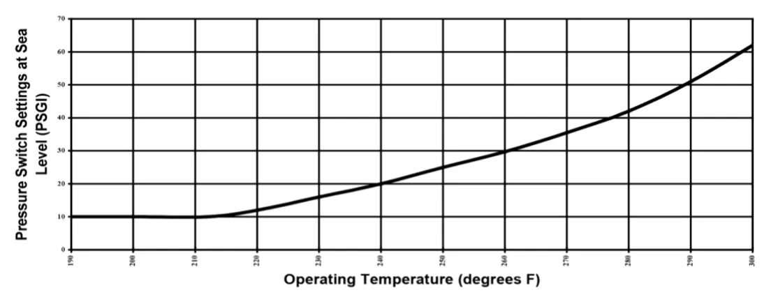
Author: G. M. Gallaspy, Jr.
Statutory Authority: Code of Ala. 1975, §§22-2-2, 22-20-7.
History: Repealed and New Rule: Filed October 18, 2018; effective December 2, 2018.