Ala. Admin. Code r. 420-3-16-AH
Appendix H - Pasteurization Equipment and Procedures and Other Equipment
Effective Dec 2, 2018Repealed and New Rule: Filed October 18, 2018; effective December 2, 2018.Alabama Department of Public Health
I. HIGH TEMPERATURE/SHORT TIME (HTST) PASTEURIZATION OPERATION OF HTST PASTEURIZATION SYSTEMS
1. Cold raw milk or milk product in a constant-level supply tank is drawn into the regenerator section of the HTST pasteurizer.
Note: Some operators prefer to bypass the regenerator when starting. Under this system, cold milk is drawn directly through the timing pump, step 3, and into the heater section. The remaining steps are performed without exception. This bypass arrangement facilitates and speeds up the starting operation. After forward-flow has been established at the FDD, the bypass, which may be manually or automatically controlled, is not used and the raw milk or milk product flows through the regenerator. A second start-up technique involves the use of sanitizing solution at 77°C (170°F). This is passed through the complete unit and followed immediately by milk or milk product. Dilution of the first milk or milk product does occur; however, care shall be taken to prevent this from being packaged.
- 2. In the regenerator section, the cold raw milk or milk product is warmed by hot pasteurized milk or milk product flowing in a counter current direction on the opposite sides of thin stainless steel surfaces.
- 3. The raw milk or milk product still under suction passes through a positive-displacement-timing pump that delivers it under pressure through the rest of the HTST pasteurization system.
- 4. The raw milk or milk product is pumped through the heater section where hot water or steam on opposite sides of thin stainless steel surfaces heats the milk or milk product to a temperature of at 72°C (161°F).
- 5. The milk or milk product at pasteurization temperature and under pressure flows through the holding tube where it is held for at least fifteen (15) seconds. The maximum velocity of the milk or milk product through the holding tube is governed by the speed of the timing pump, the diameter and length of the holding tube, and surface friction.
- 6. After passing the sensing bulbs of the indicating thermometer and recorder/controller, the milk or milk product passes into the FDD which automatically assumes a forward-flow position if the milk or milk product passes the recorder/controller bulb at the preset cut-in temperature, i.e., 72°C (161°F).
- 7. Improperly heated milk or milk product flows through the diverted-flow line back to the constant-level tank.
- 8. Properly heated milk or milk product flows through the forward-flow line to the pasteurized milk or milk product regenerator section where it serves to warm the cold raw milk or milk product and, in turn, is cooled.
- 9. The warm milk or milk product passes through the cooling section where coolant on the sides of thin stainless steel surfaces opposite the pasteurized milk or milk product reduces its temperature to 4.5°C (40°F) and below.
10. The cold pasteurized milk or milk product then passes to a storage tank or vat to await packaging.
HTST PASTEURIZERS EMPLOYING MILK OR MILK PRODUCT-TO-MILK OR MILK PRODUCT REGENERATORS WITH BOTH SIDES CLOSED TO THE ATMOSPHERE
Rule 420-3-16-.10(16) establishes standards for regenerators. These standards ensure that the raw milk or milk product will always be under less pressure than pasteurized milk or milk product in order to prevent contamination of the pasteurized milk or milk product in the event flaws should develop in the metal or joints separating it from the raw milk or milk product. An explanation of regenerator specifications is given below.
During normal operation, i.e., while the timing pump is operating, raw milk or milk product will be drawn through the regenerator at sub-atmospheric pressure. The pasteurized milk or milk product in the milk, or milk product-to-milk or milk product regenerator will be above atmospheric pressure. The required pressure differential will be assured when there is no flow-promoting device downstream from the pasteurized milk or milk product side of the regenerator to draw the pasteurized milk or milk product through the regenerator, and the pasteurized milk or milk product downstream from the regenerator rises to at least 30.5 centimeters (twelve [12] inches) elevation above the highest raw milk or milk product level downstream from the constant-level tank, and is open to the atmosphere at this or a higher elevation, as required in Item 16p(C), 420-3-16-.10(16)(iv) (refer to Administrative Procedures 2).
During a shutdown, i.e., when the timing pump stops, the raw milk or milk product in the regenerator will be retained under suction, except this suction may be gradually relieved by possible entrance of air drawn through the regenerator plate gaskets from the higher outside atmospheric pressure. With a free draining regenerator as required under Item 16p(C), Administrative Procedures 8, the raw milk or milk product level in the regenerator may drop slowly depending on the tightness of the gaskets ultimately falling below the level of the plates to the milk or milk product level in the constant-level tank. However, under these conditions, as long as any raw milk or milk product remains in the regenerator, it will be at sub-atmospheric pressure.
During shutdown, the pasteurized milk or milk product in the regenerator is maintained at atmospheric pressure or above by meeting the elevation requirement of Item 16p(C), (refer to Administrative Procedures 2). Pressure greater than atmospheric is maintained when the level of pasteurized milk or milk product is at or above the required elevation and loss of pressure due to suction is prevented by prohibiting a downstream pump.
Any backflow of milk or milk product through the FDD would lower the pasteurized milk or milk product level during pump shutdowns thus tending to reduce the pressure on the pasteurized milk or milk product side of the regenerator. An FDD cannot be relied upon to prevent backflow in such instances because during the first few minutes following a pump shutdown, the milk or milk product is still at a sufficiently high temperature to keep the FDD in the forward flow position. Compliance with the provisions of Item 16p(C), Administrative Procedures 2 and 3; however, will ensure a proper pressure differential in the regenerator.
At the beginning of a run, from the time raw milk or milk product or water is drawn through the regenerator until the pasteurized milk or milk product or water has risen to the elevation specified in Item 16p(C), Administrative Procedures 2, the pasteurized milk or milk product side of the regenerator is at atmospheric pressure or higher. Even if the timing pump should stop during this period, the pressure on the pasteurized milk or milk product side of the regenerator will be greater than the sub-atmospheric pressure on the raw milk or milk product side. This will be assured by compliance with Item 16p(C), Administrative Procedures 2 and 3, as long as any raw milk or milk product remains in the regenerator.
When a raw milk or milk product booster pump is incorporated into the HTST pasteurization system, Item 16p(C), Administrative Procedures 5 requires, in part, that automatic means shall be provided to assure, at all times, the required pressure differential between raw and pasteurized milk or milk product in the regenerator before the booster pump can operate.
THE USE OF SEPARATORS WITHIN HTST SYSTEMS
Separators in HTST pasteurization systems shall be installed and operated in such a manner that they will not adversely affect the regenerator pressures, create a negative pressure on the FDD during operation, or cause milk or milk product flow through the holding tube during times when such flow would compromise a required public health safe guard.
1. A separator may be located between the outlet of a raw regenerator and the timing pump or between raw regenerator sections if the separator is automatically valved-out of the system, and separator stuffing pump(s) are de-energized, when:
- a. The timing pump is not in operation; or
- b. A dual stem FDD is in the inspect position; or
- c. In a system with a dual stem FDD in which the separator is located between sections of a raw regenerator, during the first ten (10) minutes of a required ten (10) minute time delay in CIP mode and during any period of diverted-flow; or
d. The pressures in any raw regenerator sections located after the separator are out of compliance with the pressure requirements of these rules.
Note: The second section of a split raw regenerator shall automatically drain freely to the constant-level tank or to the floor in the event of a shut down.
- 2. A separator may not be located between the timing pump and the FDD.
3. A separator may be located on the pasteurized side of the FDD if:
- a. A properly installed atmospheric break is located between the FDD and the inlet of the separator.
- b. All milk or milk product rises to at least 30.5 centimeters (twelve [12] inches) higher than the highest raw milk or milk product in the system and is open to the atmosphere at some point between the outlet of the separator and the inlet of any pasteurized side regenerator.
- c. All milk or milk product rises to at least 30.5 centimeters (twelve [12] inches) higher than the highest raw milk or milk product in the system and is open to the atmosphere at some point between the outlet of any pasteurized side regenerator and the inlet of a separator.
d. The separator is automatically valved-out of the system, and the separator stuffing pump is de-energized.
- (1) When a dual stem FDD is in the first ten (10) minutes of a required ten (10) minute delay in CIP mode.
- (2) When the FDD is diverted in product or inspect mode.
- (3) When the timing pump is not in operation.
- (4) When the temperature is below the required pasteurization temperature and the FDD is not in the fully diverted-position.
4. The following criteria apply to installations where a separator shall be valved-out:
- a. A valve shall be located to isolate the product supply line from the separator.
- b. A valve shall be located to prevent all flow exiting the separator from being returned to the pasteurization system downstream of the separator.
- c. The valves are required to move in order to accomplish the two (2) criteria listed above and shall move to the valved-out position, and any separator stuffing pumps shall be de-energized upon loss of air or power.
5. The following criteria applies to installations where a separator is located on the raw side of a HTST system and a cream or skim balance tank(s) is not being utilized for the collection of either the cream or skim that exits the HTST system:
- a. A fail-safe (spring-to-close upon loss of air or power), block-and-bleed valve or valve arrangement shall be installed on the cream or skim line downstream from the separator and prior to any pump(s) or cream or skim storage tank(s), and shall be at least 30.5 centimeters (12 inches) below the required opening to the atmosphere on the pasteurized side of the HTST regenerator. This fail-safe valve or valve arrangement shall be closed whenever the separator is required to be automatically valved-out of the system and the separator stuffer pump is de-energized.
- b. If a computer or programmable controller is used to provide any of these required functions, it shall comply with the applicable Section(s) of Appendix H, VI.
c. If not installed in compliance with a. and b. above, the height of the cream or skim storage tank shall be considered when determining the highest raw product in the HTST system.
THE USE OF LIQUID INGREDIENT INJECTION WITHIN HTST SYSTEMS
Milk or milk product flavoring slurries, condensed milk or milk products, and cream or skim milk for standardization and similar ingredients may be injected at a point after the last regenerator and before the timing pump, if all of the following conditions are met:
1. The slurry injection valve(s) is (are) closed and the slurry pump is de-energized:
- a. When the FDD is in the “Inspect” mode.
- b. When the timing pump is not in operation.
c. When the temperature is below the required minimum legal pasteurization temperature and the FDD is not in the fully diverted position.
- (1) A spring-to-close and air-to-open blocking valve is located between the slurry injection pump and the slurry injection valve(s) described in 2 below.
- (2) All valves shall be inter-wired to assure they fully isolate the slurry pump from the pasteurization system when the FDD is not in the forward-flow position or whenever any flow-promoting device(s) which is (are) upstream of the FDD and (are) capable of generating flow through the FDD is (are) not in operation.
Note: The slurry pump may remain energized provided:
- 2. The slurry injection valve(s) is (are) of the fail-safe type, spring-to-close and air-to-open, and are “block-and-bleed” design with a full port open to the atmosphere between the HTST isolation seat and the slurry pump when slurry is not being injected.
- 3. The slurry piping between the slurry pump and the injection point may rise to a height that is higher than the overflow level of the slurry supply tank(s), but is at least 30.5 centimeters (twelve [12] inches) lower than the required opening to the atmosphere on the pasteurized side.
- 4. The slurry supply tank has an overflow that is at least twice the diameter of the largest inlet pipe, or all inlet pipes are disconnected and the openings capped during operation of the slurry pump.
- 5. There is a check-valve in the flow stream of the milk or milk product line from the last regenerator, typically after the separator, upstream of the injection point valve.
- 6. For a milk or milk product flavoring slurry that contains milk and/or milk products, the tanks and/or vessels used to blend and hold the slurry shall be completely emptied and cleaned after each four (4) hours of operation or less, unless the slurry is stored at a temperature of 7°C (45°F) or less, or at a temperature of 66°C (150°F) or greater, and maintained thereat until the time of injection.
- 7. If computers or programmable controllers are used to provide any of these required functions, they shall meet the applicable portion of Appendix H, VI.
8. Appropriate test procedures shall be provided to evaluate the required inter-wiring and function.
- a. Self-diagnostic circuitry that provides constant monitoring of all sensing, input, and conditioning circuits. The diagnostic circuitry shall be capable of detecting “open” circuits, “short” circuits, poor connections, and faulty components. Upon the detection of a failure of any component, the magnetic flow meter read-out shall be blank or become unreadable.
- b. The electro-magnetic compatibility of the magnetic flow meter shall be documented and available to the Health Officer. The magnetic flow meter shall be tested to determine the effects of electrostatic discharge, power fluctuation, conductive emission and susceptibility, and radiative emission and susceptibility.
- c. The effect of exposure to specific environmental conditions shall be documented. The magnetic flow meter shall be tested to determine the effects of low and high temperatures, thermal shock, humidity, physical shock, and salt fog.
- d. The magnetic flow meter converter or transmitter and flow sensor, for those magnetic flow meters in which flow sensor sealing is required, shall be constructed so that they can be sealed by the Health Officer.
- e. The calibration of the magnetic flow meter shall be protected against unauthorized changes.
- f. The magnetic flow meter shall be protected against unauthorized converter or transmitter replacement. If flow tubes are replaced, the Health Officer shall be notified and such replacement shall be regarded as a replacement of the magnetic flow meter and subject to the Health Officer’s inspection and all applicable tests under Appendix I.
g. The flow tube shall be encased in appropriate material and constructed in such a manner that the final assembly complies with the conditions cited within Item 11p 420-3-16-.10(11).
Calibration - The calibration shall be based on multiple points for the entire range of the magnetic flow meter for MFMBTS application. The magnetic flow meter shall be tested against a traceable National Institute of Standards and Technology (NIST) standard. The procedure(s) used for the magnetic flow meter calibration is documented and available to the Health Officer.
Accuracy - At mid-range, six (6) consecutive flow measurements are taken at the same flow setting. From these six (6) measurements, the standard deviation is calculated. The standard deviation for these measurements shall be less than 0.5 percent. Compliance of the determined through the actual installation field-testing of the magnetic flow meter.
Note: This section describes one (1) method that has been reviewed and accepted for this purpose. It does not preclude other methods that may be reviewed and found acceptable.
In order to help assure compliance with Section 2-Adulteration, the Health Officer may require that the milk plant close the slurry valve and de-energize the slurry pump during times when the system is recycling milk or milk product, such as in recycle mode, diverted-flow, or the first ten (10) minutes of the CIP cycle. If a computer is used to accomplish this, it does not need to meet Appendix H and VI.
PRESSURE RELIEF VALVES LOCATED DOWNSTREAM FROM THE HOLDING TUBE WITHIN HTST PASTEURIZATION SYSTEMS
The pressures in the pasteurized side of the regenerator shall be protected from falling within 6.9 kPa (1 psi) of the pressures in the raw side of the regenerator at all times, including during shut down. A pressure relief valve on the pasteurized side of the FDD will meet this criterion if the pressure relief valve is fail-safe. A leaking pressure relief valve can cause an unacceptable loss of pressure in the pasteurized side of the regenerator during a shut down and is considered a violation of Item 16p(C) 420-3-16-.10(19). Any leakage from this pressure relief valve shall be readily visible. This may be accomplished by opening the pressure relief valve vent directly to the floor or by providing sanitary piping from the pressure relief valve vent to the constant-level tank. If the latter option is utilized, the piping shall be properly sloped to assure drainage to the constant-level tank and shall be provided with a properly located and installed sight-glass.
POSITION DETECTION DEVICES
Where the position detectability of FDDs and valve seats is required this may be accomplished by mechanical or electronic means, such as mechanical limit switches (micro-switches) or electronic proximity switches. These switches shall be capable of providing an electrical signal when the valve seat is in the fully closed position, provided further that the position detection capability is fully testable.
Position detection devices (PDDs) shall be repeatable and capable of detecting valve seat movement of less than 3.18 mm (1/8 [0.125] of an inch) at all times.
MAGNETIC FLOW METER BASED TIMING SYSTEMS WITHIN CONTINUOUS FLOW PASTEURIZATION SYSTEMS
Many pasteurization systems use magnetic flow meter based timing systems (MFMBTS). The flow through these timing systems is developed by a combination of flow promoting devices including booster and stuffer pumps, separators and clarifiers, homogenizers, and positive displacement pumps.
Item 16p.(B)2(f), Section 7 provides for their use, provided they meet the following specifications for design, installation, and use.
Components - MFMBTS shall consist of the following components:
A magnetic flow meter which has been reviewed by FDA or one (1) which meets the following criteria for accuracy and reliability:
- 2. Suitable converters for conversion of electric and/or air signals to the proper mode for the operation of the system.
- 3. A suitable flow recorder capable of recording flow at the flow alarm set point and also at least nineteen (19) liters (five [5] gallons) per minute higher than the flow alarm setting. The flow recorder shall have an event pen that shall indicate the status of the flow alarm with respect to flow rate.
4. A flow alarm, with an adjustable set point shall be installed within the system which shall automatically cause the FDD to be moved to the divert position whenever excessive flow rate causes the milk or milk product holding time to be less than the legal holding time for the pasteurization process being used. The flow alarm shall be tested by the Health Officer in accordance with the procedures of Appendix I, Test 11, 2.A and B at the frequency specified. The flow alarm adjustment shall be sealed.
Note: Test 11, 2.A is not applicable to HHST pasteurization systems.
- 5. A low-flow or loss-of-signal alarm shall be installed with the system, which shall automatically cause the FDD to be moved to the divert position whenever there is a low-flow or loss-of-signal from the magnetic flow meter. The low-flow or loss-of-signal provision shall be tested by the Health Officer in accordance with Appendix I, Test 11, 2.C at the frequency specified. The low-flow or loss-of-signal provision shall be sealed.
6. For HTST systems, when the legal flow rate has been reestablished following an excessive flow rate, a time delay shall be instituted which shall prevent the FDD from assuming the forward-flow position for at least a minimum of fifteen (15) or twenty-five (25) seconds depending upon the product being pasteurized and the temperature being utilized. The time delay shall be tested and sealed by the Health Officer.
For HHST systems, when the legal holding time has been reestablished following an excessive flow rate, a time delay at least as long as the legal flow rate shall be instituted which shall prevent the FDD from assuming the forward-flow position until at least the legal holding time within the holding tube has been reestablished. This time delay shall be built into the sequencelogic that requires all conditions for legal pasteurization to be satisfied and that legal pasteurization temperature exists from the holding tube to the FDD, before the FDD can assume the forward-flow position.
7. For HTST systems, a sanitary check valve or normally closed automatically controlled sanitary valve shall be installed with the magnetic flow meter to prevent a positive pressure in the raw milk or milk product side of the regenerator whenever a power failure, shutdown, or flow-diversion occurs.
Note: This provision is not applicable to HHST pasteurization systems.
8. For HTST systems, when a regenerator is used with large systems, it will be necessary to bypass the regenerator during start-up and when the FDD is in the diverted-flow position. Care shall be taken in the design of such bypass systems to assure that a dead-end does not exist. A dead-end could allow milk or milk product to remain at ambient temperature for long periods of time and allow bacterial growth in the milk or milk product. Caution shall also be observed with such bypass systems and any valves used in them so that raw milk or milk product will not be trapped under pressure in the raw regenerator plates and not have free drainage back to the constant-level tank when shutdown occurs.
Note: This provision is not applicable to HHST pasteurization systems.
- 9. When switching to the “CIP” position, the FDD shall move to the divert position and shall remain in the diverted-flow position for at least ten (10) minutes, regardless of temperature, and for HTST pasteurization systems, the booster pump cannot run during this ten (10) minute time delay.
- 10. All MFMBTS pasteurization systems shall be designed, installed, and operated so that all applicable tests required by 420-3-16-.10(21), Item 16p(D) can be performed by the Health Officer, at the frequency specified (refer to Appendix I). Where adjustment or changes can be made to these devices or controls, appropriate seals shall be applied by the Health Officer after testing so that changes cannot be made without detection.
11. Except for those requirements directly related to the physical presence of the timing pump, all other requirements of the most recent edition of these rules are applicable.
Placement of Components - Individual components in an MFMBTS shall comply with the following placement conditions:
- 1. The timing system’s flow promoting device(s) shall be located upstream from the magnetic flow meter.
- 2. The magnetic flow meter shall be placed after the last raw product regenerator outlet and upstream of the holding tube. There shall be no intervening flow-promoting components between the magnetic flow meter and the holding tube.
3. For HTST pasteurization systems, when a sanitary check valve or normally closed automatically controlled sanitary valve, as described in #7 above, is used with a variable or constant speed flow promoting device, it shall be located downstream of the last regenerator outlet and upstream of the holding tube.
Note: This provision is not applicable to HHST pasteurization systems.
- 4. All flow-promoting devices which are upstream of the FDD and which are capable of generating flow through the FDD, shall be properly interwired with the FDD so that they may run and produce flow through the system at sub-legal temperatures only when the FDD is in the fully diverted position and in “Product” run mode, or “CIP” mode after the ten (10) minute time delay has timed out. Such flow promoting devices shall be de-energized in “Inspect” mode. Separators or clarifiers that continue to run after they are de-energized shall be automatically valved-out of the system with fail-safe valves so that they are incapable of producing flow.
- 5. There shall not be any product entering or leaving the pasteurization system, i.e., cream or skim milk from a separator or other product components, between the magnetic flow meter and the holding tube.
- 6. The magnetic flow meter shall be so installed that the milk or milk product has contact with both electrodes at all times when there is flow through the system. This is most easily accomplished by mounting the flow tube of the magnetic flow meter in a vertical position with the direction of flow from the bottom to the top. However, horizontal mounting is acceptable when other precautions are taken to assure that both electrodes are in contact with the product and the horizontal line shall remain full of liquid during operation. Magnetic flow meters shall not be mounted on a horizontal line that may be only partially full and thereby trap air.
7. The magnetic flow meter shall be piped in such a manner that at least ten (10) pipe diameters of straight pipe exists, upstream and downstream from the center of the magnetic flow meter, before any elbow or change of direction takes place. Except that other piping configurations upstream and downstream of the magnetic flow meter may also be used if they have been reviewed and found acceptable to FDA and the Health Officer.
THE USE OF VACUUM BREAKERS ON HTST SYSTEMS
Vacuum breakers are often used on HTST pasteurization systems to help maintain proper pressure relationships in milk-to-milk regenerator sections, or to prevent a negative pressure between the FDD and any downstream flow-promoting device. The use of vacuum breakers on HTST pasteurization systems is allowed provided the following conditions are met:
- 1. Vacuum breakers shall open to the atmosphere when subject to a negative pressure.
2. The pasteurized milk and milk product between its outlet from the regenerator and the nearest point downstream open to the atmosphere shall rise to a vertical elevation of 30.5 centimeters (12 inches) above the highest raw milk or milk product level, downstream from the constant- level tank, and shall be open to the atmosphere at this or a higher elevation.
Spring-to-close vacuum breakers are not allowed.
HTST AND HHST FLOW DIAGRAMS
Figure 31. HTST Pasteurizer with a Positive Displacement Rotary Timing Pump
Figure 32. HTST Pasteurizer with a Homogenizer Located at the Outlet of the Heater Section and of a Larger Capacity than the Timing Pump
Figure 33. HTST Pasteurizer with a Booster Pump, Meter Based Timing System and a Homogenizer with a Bypass Line
Figure 34. HTST Pasteurizer with a Booster Pump, Timing Pump, and a CIP-Type Separator Located Between Two Pasteurized Product Regenerators with a Pre-Heater
Figure 35. HTST Pasteurizer with a Booster Pump, Homogenizer as a Timing Pump with an AC Variable Frequency Drive, CIP-Type Separator Located Between Two Pasteurized Product Regenerators and an Air Actuated Discharge Valve with an Air Blow
Figure 36. HTST Pasteurizer with a Separator Between the Raw Regenerator and the Heater Section with a Meter Based Timing System and a Regenerator Bypass
Figure 37. HTST Pasteurizer Utilizing Tubular Type Heat Exchangers and a Homogenizer as the Timing Pump
Figure 38. HTST Pasteurizer, without a Regenerator or Cooler Section, with a Meter Based Timing System Located Upstream from an Evaporator
Figure 39. HTST Pasteurizer with a Regenerator, Separator, Skim Surge Tank, and a Meter Based Timing System Located Upstream from an Evaporator Pump
Figure 40. HHST Pasteurizer with a Flow-Diversion Device Located Downstream of the Cooling Section
Figure 41. HHST Pasteurizer Utilizing Steam Injection Heating, Vacuum Flash Cooling, and a Flow-Diversion Device Located Downstream of the Cooler Section Pump
Figure 42. HHST Pasteurizer Utilizing Direct Culinary Steam Infusion and Vacuum Flash Cooling with a Homogenizer Located Downstream
Figure 43. HHST Pasteurizer with a Homogenizer as the Timing Pump and Utilizing a Spiral Tubular Heat Exchanger with Indirect Regeneration
HTST pasteurization is important to the dairy industry because of the operating efficiencies that it affords. Properly operated, these units allow a high volume of production in a minimum of processing space.
The ability of HTST pasteurizers to assure a safe, finished milk and/or milk product hinges on the reliability of the time-temperature-pressure relationships that must prevail whenever the system is in operation. It is important that the milk plant operator understand the HTST process in order to maintain proper surveillance over the equipment. The basic flow pattern is described below:
II. AIR FOR DRYING EQUIPMENT AND AIR UNDER PRESSURE - DIRECT CONTACT WITH MILK AND MILK PRODUCTS AND MILK PRODUCT-CONTACT SURFACES
- a. Use of a carbon ring piston compressor;
- b. Use of oil-lubricated compressor with effective provision for removal of any oil vapor by cooling the compressed air; or
c. Water-lubricated or non-lubricated blowers.
The air supply shall be taken from a clean space or from relatively clean outer air and shall pass through a filter upstream from the compressing equipment. This filter shall be located and constructed so that it is easily accessible for examination and the filter media are easily removable for cleaning or replacing. The filter shall be protected from weather, drainage, water, product spillage, and physical damage.
Moisture Removal Equipment - Air under pressure systems in excess of one (1) bar, i.e., 103.5 kPa (15psi), shall be provided with methods of moisture removal. The removal of moisture may be achieved by condensation and coalescing filtration or absorption, or equivalent, to prevent free water in the system. If it is necessary to cool the compressed air, an after-cooler shall be installed between the compressor and the air storage tank for the purpose of removing moisture from the compressed air.
Filters and Moisture Traps - Filters shall be constructed so as to assure effective passage of air through the filter media only. The coalescing filter and associated traps shall be located in the air pipeline downstream from the compressing equipment, and from the air tank, if one is used. The filter shall be readily accessible for examination, cleaning, and for replacing the filter media. The moisture trap shall be equipped with a petcock or other means for draining accumulated water (refer to Figures 44, 45, and 48).
When coalescing filters are used, a means shall be provided to measure the differential pressure across the filter. The differential pressure device is required to indicate the need for filter media replacement.
All coalescing filter housings shall be provided with a means of removing the condensed liquid from the filtration device. This can be accomplished by an automatic or manual drain installed on the base of the filter housing.
The final filter media shall be disposable. The filter media shall be located in the air line upstream from, and as close as possible to, the point of application (refer to Figures 44, 45 and 48). Except that a final filter shall not be required where the compressing equipment is of a fan or blower type and operating at a pressure of less than one (1) bar, i.e., 103.5 kPa (15psi) (refer to Figures 46 and 47).
Electronic air cleaners utilizing electrostatic precipitation principles to collect particulate matter may be used. Disposable filter media shall not be cleaned and reused.
Air Piping - The air piping from the compressing equipment to the filter and moisture trap shall be readily drainable.
A milk or milk product check-valve of sanitary design shall be installed in the air piping downstream from the disposable media filter to prevent backflow of milk or milk product into the air pipeline, except that a check-valve shall not be required if the air piping enters the milk or milk product zone from a point higher than the milk or milk product overflow level which is open to the atmosphere or is for dry product applications or for other dry application where liquids are not present.
When a check-valve is not required, plastic or rubber or rubber-like tubing and suitable compatible fittings and connections made of plastic or stainless steel may be used between the final filter and the point of application.
Air distribution piping and fittings after the final filter shall be of corrosion-resistant materials. Air distribution piping, fittings, and gaskets between the discharge of the sanitary check-valve to the processing equipment shall be sanitary piping that conforms to the requirements of Item 10p, Rule 420-3-16-.10(10), except that:
When air under pressure is directed at product-contact surfaces of containers, closures, and supplementary fitments, the air passage from the final filter to the point of application shall be made of a non-toxic, relatively nonabsorbent material. In this application, check-valves are not
required. The final filter shall be located as close as practical to the point of application (refer to Figure 48).
When used for air agitation, tubing used to introduce air into the product and/or product zone shall be sanitary piping that conforms to the requirements of Item 10p, Rule 420-3-16-.10(10). There shall be no threads on product-contact surfaces. When drilled or perforated pipe is used, internal drilling burrs shall be removed and the orifices shall be chambered on the outer surface of the pipe. If the volume of the air from the compressing equipment is in excess of that required for satisfactory agitation, suitable means shall be employed to eliminate the excess volume.
Note: For additional details, refer to the 3-A Accepted Practices for Supplying Air Under Pressure in Contact with Milk, Milk Products and Product-Contact Surfaces 604-## and 3-A Accepted Practices for Spray Drying Systems 607##.
Figure 44. Individual Compression-Type Air Supply
1. Compressing Equipment 7. Final Filter 2. Drain Valve 8. Product Contact Valve (Where Required) 3. After-cooler (When Used) 9. Sanitary Piping Downstream From This Point 4. Pressure Gauge (Optional) 10. To Point of Application 5. Dryer (When Used) 11. Intake Air Filter 6. Air Pipe Line Coalescing Filter and Moisture Trap Figure 45. Central Compression-Type Air Supply
1. Compressing Equipment 10. Final Filter 2. Intake Air Filter 11. To Point of Application 3. After-cooler 12. Drain Valve 4. Sanitary Relief Valve 13. Moisture Leg or Trap 5. Air Pipe Line Coalescing Filter and 14. Air Storage Tan 6. Moisture Trap Pressure Gauge (Optional) 15. Air Gap 7. Dryer (When Used) 16. Trap and Drain Valve 8. Sanitary Piping Downstream From This Point 17. Condensate Pip 9. Product Check-Valve (Where Required) Figure 46. Individual Blower-Type Air Supply
1. Blower or Fan, 34.5-103.5 kPa (5-15 psi) 4. To Point of Application 2. Air Line or Duct 5. Final Filter (When Used) 3. Pressure Gauge (When Used) 6. Intake Air Filter Figure 47. Individual Fan-Type Air Supply
AIR FOR DRYING EQUIPMENT
Filter Media - Intake air filter media shall consist of fiberglass with a downstream backing dense enough to prevent fiberglass break off from passing through cotton flannel, wool flannel, spun metal, activated carbon, activated alumina, non-woven fabric, absorbent cotton fiber, electrostatic, or other suitable materials which, under conditions of intended use, are non-toxic and non-shedding and which do not release toxic volatiles or other contaminants to the air, or volatiles which impart any flavor or odor to the milk or milk product. Chemical bonding materials contained in the media shall be non-toxic, non-volatile, and insoluble under all conditions of use. Disposable media are not intended to be cleaned and re-used. Electronic air cleaners using electrostatic precipitation principles to collect particulate matter may be used in spray drying systems only as a pre-filter.
Filter Performance - The air supply system and/or ducting shall be such that the air supply is caused to pass through suitable air filters, properly installed, before coming in contact with milk product-contact surfaces of the drying system. Supply air filters for air which will be heated before it comes in contact with the milk or milk product shall be of a design selected to operate at a face velocity, and installed in a manner which will allow the filter manufacturer's rating to be 90 percent or higher, when tested in accordance with the American Society of Heating, Refrigerating and Air-Conditioning Engineers (ASHRAE) Synthetic Dust Arrestance Test.1 Supply air filters for air which will not be heated before it comes in contact with the milk or milk product shall be of a design selected to operate at a face velocity, and installed in a manner which will allow the filter manufacturer's rating to be 85 percent or higher when tested in accordance with the ASHRAE Atmospheric Dust Spot Method.2
AIR UNDER PRESSURE - MILK PRODUCT-CONTACT SURFACES
Filter Media - Air intake and pipeline filters shall consist of fiberglass with a downstream backing dense enough to prevent fiberglass break off from passing through cotton flannel, wool flannel, spun metal, electrostatic material or other equally acceptable filtering media which are non-shedding and which do not release to the air, toxic volatiles or volatiles which may impart any flavor or odor to the milk or milk product.
Filter Performance - Intake air filter efficiency shall be at least 98 percent SAE J7263, June 19874 using Air Cleaner (AC) coarse test dust. Final filter efficiency shall be at least 99 percent as measured by the Dioctylphthalate Fog Method (DOP) test (with a mean particle diameter of 0.3 microns).5 When commercially sterile air is required, the final filter efficiency shall be at least 99.99 percent as measured by the DOP test.
__________________________________________
1 Method of Testing Air Cleaning Devices, ASHRAE Standard 52 (available from the American Society of Heating, Refrigerating and Air Conditioning Engineers
2 Method of Testing Air Cleaning Devices, ASHRAE Standard 52 (available from the American Society of Heating, Refrigerating and Air Conditioning Engineers
3 Dill, R. S., A Test Method for Air Filters. Transactions of the American Society of Heating and Ventilation engineers. 44:379, 1938. Society of Automotive Engineers, 400 Commonwealth Drive, Warrendale, Pennsylvania 15096-0001 (412) 776-4841.
4 DOP Smoke Penetration and Air Resistance of filters. Military Standard No. 282. Section 102.91. Naval Supply Depot, 5801 Tabor Avenue, Philadelphia, Pennsylvania 19120.
5 MIL-STD-282-Military Standard 282: Method 102.91: Dicoctyphthalate Fog Method (DOP). Standardization, Document Order Desk (Department of Navy), 700 Robinson Avenue, Building 4, Section D. Philadelphia, PA 1911-5094.FABRICATION AND INSTALLATION
Air Supply Equipment - The compressing equipment shall be designed to preclude contamination of the air with lubricant vapors and fumes. Oil-free air may be produced by one of the following methods or their equivalent:1. Blower or Fan, Below 34.5 kPa (5 psi)
2. Intake Air Filter
3. To Point of ApplicationFigure 48. Rotating Mandrel Assembly
1. Compressing Equipment 6. Dryer (When Used 2. After-cooler (When Used 7. Final Filter 3. Pressure Gauge (When Used 8. Intake Air Filter 4. Air Pipeline Coalescing Filter and Moisture Trap 9. Fixed Air Passage 5. Drain Valve 10. Rotating Mandrel Assembly III. CULINARY STEAM – MILK AND MILK PRODUCTS
The following methods and procedures will provide steam of culinary quality for use in the processing of milk and milk products.
SOURCE OF BOILER FEED WATER
Potable water or water supplies acceptable to the Health Officer shall be used.
FEED WATER TREATMENT
Feed water may be treated, if necessary, for proper boiler care and operation. Boiler feed water treatment and control shall be under the supervision of trained personnel or a firm specializing in industrial water conditioning. Such personnel shall be informed that the steam is to be used for culinary purposes. Pretreatment of feed waters for boilers or steam generating systems to reduce water hardness before entering the boiler or steam generator by ion exchange or other acceptable procedures is preferable to the addition of conditioning compounds to boiler waters. Only compounds complying with 21 CFR 173.310 may be used to prevent corrosion and scale in boilers or to facilitate sludge removal. Greater amounts shall not be used of the boiler water treatment compounds than the minimum necessary for controlling boiler scale or other boiler water treatment purposes. No greater amount of steam shall be used for the treatment and/or pasteurization of milk and milk products than necessary.
It should be noted that tannin, which is also frequently added to boiler water to facilitate sludge removal during boiler blow-down, has been reported to give rise to odor problems and should be used with caution.
Boiler compounds containing cyclohexylmine, morpholine, octadecylamine, diethylamino-ethanol, trisodium nitrilotriacetae, and hydrazine shall not be permitted for use in steam in contact with milk and milk products.
BOILER OPERATION
A supply of clean, dry saturated steam is necessary for proper equipment operation. Boilers and steam generation equipment shall be operated in such a manner as to prevent foaming, priming, carryover, and excessive entrainment of boiler water into the steam. Carryover of boiler water additives can result in the production of milk or milk product off-flavors. Manufacturers' instructions regarding recommended water level and blow-down should be consulted and rigorously followed. The blow-down of the boiler should be carefully watched so that an over- concentration of the boiler water solids and foaming is avoided. It is recommended that periodic analyses be made of condensate samples. Such samples should be taken from the line between the final steam separating equipment and the point of the introduction of steam into the milk or milk product.
PIPING ASSEMBLIES
Refer to Figures 49 and 50 for suggested piping assemblies for steam infusion or injection. Other assemblies that will assure a clean, dry saturated steam are acceptable.
Figure 49 - Culinary Steam Piping Assembly for Steam Infusion or Injection
1. Steam Main Device 9. *Differential Pressure Measuring Device 2. Stop Valve 10. *Filtering Device 3. Strainer 11. *Stainless Steel (from this point) 4. *Entrainment Separator 12. *Sanitary Piping and Fittings (from this point) 5. *Condensate Trap 13. *Spring-loaded Sanitary Check Valve 6. Pressure Gauge 14. *Sanitary Piping To Process Equipmen 7. Steam Pressure Regulating (reducing) Valve 15. *Sampling Means 8. Steam Throttling Valve (automatic or manual) or Orifice *Required Equipment
Figure 50 - Culinary Steam Piping Assembly for Steam Infusion or Injection (Optional Configuration)
Figure 51 - Culinary Steam Piping Assembly for Airspace Heating or Defoaming
IV. THERMOMETER SPECIFICATIONS INDICATING THERMOMETERS FOR BATCH PASTEURIZERS
1. Mercury Actuated Direct Reading
- a. Contained in a corrosion-resistant case which protects against breakage and permits easy observation of the column and scale.
- b. Filling above mercury-nitrogen or other suitable gas.
- c. The mercury column shall be magnified to an apparent width of not less than 1.6 millimeters (0.0625 of an inch).
2. Digital Stand Alone
- a. No more than 0.2°C (0.5°F) drift over three (3) months use on a batch pasteurizer compared to a certified temperature source.
- b. Self-diagnostic circuitry which provides constant monitoring of all sensing, input, and conditioning circuits. The diagnostic circuitry should be capable of detecting “open” circuits, “short” circuits, poor connections, and faulty components. Upon detection of failure of any component, the device shall be blank or become unreadable.
- c. The electromagnetic compatibility of this device for this use shall be documented and available to the Health Officer. The device shall be tested to determine the effects of electrostatic discharge, power fluctuation, conductive emission and susceptibility, and radiative emission and susceptibility. The device shall comply with the requirements for performance level characteristics of industrial devices.
- d. The effect of exposure to specific environmental conditions shall be documented. The device shall be tested to determine the effects of low and high temperatures, thermal shock, humidity, physical shock, and salt fog.
- e. Both the probe and the display case shall be constructed so that they may be sealed by the Health Officer.
- f. Calibration of the device shall be protected against unauthorized changes.
- g. The device shall be protected against unauthorized component or sensing element replacement. Replacement of any component or sensing element shall be regarded as a replacement of the indicating thermometer and subject to the Health Officer’s inspection and all application tests under Appendix I.
- h. The sensing element shall be encased in appropriate material constructed in such a way that the final assembly meets the conditions of Item 11p 420-3-16-.10(11).
- i. The device shall be tested from the sensing probe through the final output.
3. Digital Combination
- a. No more than 0.2°C (0.5°F) drift over three (3) months use on a batch pasteurizer compared to a certified temperature source.
- b. Self-diagnostic circuitry which provides constant monitoring of all sensing, input, and conditioning circuits. The diagnostic circuitry should be capable of detecting “open” circuits, “short” circuits, poor connections, and faulty components. Upon detection of failure of any component, the temperature sensors output signal and indicating display shall go visibly out of range.
- c. The electromagnetic compatibility of this device for this use shall be documented and available to the Health Officer. The device shall be tested to determine the effects of electrostatic discharge, power fluctuation, conductive emission and susceptibility, and radiative emission and susceptibility. The device shall comply with the requirements for performance level characteristics of industrial devices.
- d. The effect of exposure to specific environmental conditions shall be documented. The device shall be tested to determine the effects of low and high temperatures, thermal shock, humidity, physical shock, and salt fog.
- e. Both the probe and the display case shall be constructed so that they may be sealed by the Health Officer.
- f. Calibration of the device shall be protected against unauthorized changes.
- g. The device shall be protected against unauthorized component or sensing element replacement. Replacement of any component or sensing element shall be regarded as a replacement of the indicating thermometer and subject to the Health Officer’s inspection and all application tests under Appendix I.
- h. The sensing element shall be encased in appropriate material constructed in such a way that the final assembly meets the conditions of Item 11p.
i. The device shall be tested from the sensing probe through the final output.
Scale - Shall have a span of not less than 14° (25°F), including the pasteurization temperature, ± 2.5°C (± 5°F); graduated in 0.5°C (1ºF) divisions, with not more than 9°C (16°F) per 2.54 centimeters (1 inch) of span; and protected against damage at 105°C (220°F). Provided, that on batch pasteurizers used solely for thirty (30) minute pasteurization of milk and milk products at temperatures above 71°C (160°F), indicating thermometers with 1°C (2°F) scale graduations, with not more than 6°C (28°F) per 2.54 centimeters (1 inch) of scale, may be used.
Accuracy - Within ± 0.2°C (± 0.5°F), through the specified scale span. Provided, that on batch pasteurizers used solely for thirty (30) minute pasteurization of milk and milk products at temperatures above 71°C (160°F), indicating thermometers shall be accurate to within ±.5°C (± 1°F) (refer to Appendix I, Test 1).
Submerged Stem Fitting - A pressure-tight seat against the inside wall of the holder; no threads exposed to milk or milk products; and the location of this seat to conform to the 3-A Sanitary Standard for a wall-type fitting or other equivalent sanitary fitting.
Bulb - Corning normal or equally suitable thermometric glass.
INDICATING THERMOMETERS LOCATED ON PASTEURIZATION PIPELINES
Type
1. Mercury Actuated Direct Reading
- a. Contained in a corrosion-resistant case which protects against breakage and permits easy observation of the column and scale.
- b. Filling above mercury - nitrogen or other suitable gas.
- c. The mercury column shall be magnified to an apparent width of not less than 1.6 millimeters (0.0625 of an inch).
2. Digital
- a. No more than 0.2°C (0.5°F) drift over three (3) months use on a HTST system compared to a certified temperature source.
- b. Self-diagnostic circuitry which provides constant monitoring of all sensing, input, and conditioning circuits. The diagnostic circuitry should be capable of detecting “open” circuits, “short” circuits, poor connections and faulty components. Upon detection of failure of any component, the device shall blank or become unreadable.
- c. The electromagnetic compatibility of this device for this use shall be documented and available to the Health Officer. The device shall be tested to determine the effects of electrostatic discharge, power fluctuation, conductive emission and susceptibility, and radiative emission and susceptibility. The device shall comply with the requirements for performance level characteristics of industrial devices.
- d. The effect of exposure to specific environmental conditions shall be documented. The device shall be tested to determine the effects of low and high temperatures, thermal shock, humidity, physical shock, and salt fog.
- e. Both the probe and the display case shall be constructed so that they may be sealed by the Health Officer.
- f. Calibration of the device shall be protected against unauthorized changes.
- g. The device shall be protected against unauthorized component or sensing element replacement. Replacement of any component or sensing element shall be regarded as a replacement of the indicating thermometer and subject to the Health Officer’s inspection and all applicable tests under Appendix I.
- h. The sensing element shall be encased in appropriate material constructed in such a way that the final assembly meets the conditions of Item 11p.
i. The device shall be tested from the sensing probe through the final output.
Scale: Shall have a span of not less than 14°C (25°F), including the pasteurization temperature, ± 2.5°C (± 5°F); and protected against damage at 105°C (220°F), and in the case of thermometers used on HHST pasteurization systems protected against damage at 149°C (300°F). Mercury actuated thermometers shall be graduated in 0.2°C (0.5°F) divisions with not more than 4°C (8°F) per 2.54 centimeters (one [1] inch) of scale. The digital thermometer readout shall display in units no greater than of 0.05°C (0.1°F).
Accuracy: Within ± 0.2°C (± 0.5°F), throughout the specified scale span (refer to Appendix I, Test 1).
Stem Fittings: A pressure-tight seat against the inside wall of the fittings; no threads exposed to milk or milk products. The probe is to be designed so that the sensitive area is discernible from the remainder of the stem. The overall probe length to be such that the sensitive area is positioned in the milk or milk product flow path when properly installed.
Thermometric Response: When the thermometer is at room temperature and then is immersed in a well-stirred water bath 11°C (19°F) or less above the pasteurization temperature, the time required for the reading to increase from water bath temperature, minus 11°C (19°F), to water bath temperature, minus 4°C (7°F), shall not exceed four (4) seconds. The digital thermometer displays shall change at a rate that can be noted by the operator or Health Officer during the thermometric lag test (refer to Appendix I, Test 7).
Bulb: Corning normal or equally suitable thermometric glass.
AIRSPACE INDICATING THERMOMETER FOR BATCH PASTEURIZERS
Type
1. Mercury Actuated Direct Reading
- a. Contained in a corrosion-resistant case which protects against breakage and permits easy observation of the column and scale.
- b. The bottom of the bulb chamber shall not be less than fifty-one (51) millimeters (two [2] inches) and not more than eighty-nine (89) millimeters (3.5 inches), below the underside of the cover.
- c. Filling above mercury-nitrogen or other suitable gas.
- d. The mercury column shall be magnified to an apparent width of not less than 1.6 millimeters (0.0625 of an inch).
- 2. Digital Stand Alone
- a. No more than 0.2°C (0.5°F) drift over three (3) months use on a batch pasteurizer compared to a certified temperature source.
- b. Self-diagnostic circuitry which provides constant monitoring of all sensing, input, and conditioning circuits. The diagnostic circuitry should be capable of detecting “open” circuits, “short” circuits, poor connections, and faulty components. Upon detection of failure of any component, the device shall be blank or become unreadable.
- c. The electromagnetic compatibility of this device for this use shall be documented and available to the Health Officer. The device shall be tested to determine the effects of electrostatic discharge, power fluctuation, conductive emission and susceptibility, and radiative emission and susceptibility. The device shall comply with the requirements for performance level characteristics of industrial devices.
- d. The effect of exposure to specific environmental conditions shall be documented. The device shall be tested to determine the effects of low and high temperatures, thermal shock, humidity, physical shock, and salt fog.
- e. Both the probe and the display case shall be constructed so that they may be sealed by the Health Officer.
- f. Calibration of the device shall be protected against unauthorized changes.
- g. The device shall be protected against unauthorized component or sensing element replacement. Replacement of any component or sensing element shall be regarded as a replacement of the indicating thermometer and subject to the Health Officer’s inspection and all application tests under Appendix I.
- h. The sensing element shall be encased in appropriate material constructed in such a way that the final assembly meets the conditions of Item 11p Rule 420-3-16-.10(11).
- i. The device shall be tested from the sensing probe through the final output.
- j. The bottom of the bulb chamber is not less than fifty-one (51) millimeters (two [2] inches) and not more than eight-nine (89) millimeters [3.5 inches], below the underside of the cover.
3. Digital Combination:
- a. No more than 0.2°C (0.5ºF) drift over three (3) months use on a batch pasteurizer compared to a certified temperature source.
- b. Self-diagnostic circuitry which provides constant monitoring of all sensing, input, and conditioning circuits. The diagnostic circuitry should be capable of detecting “open” circuits, “short” circuits, poor connections, and faulty components. Upon detection of failure of any component, the temperature sensors output signal and indicating display shall go visibly out of range.
- c. The electromagnetic compatibility of this device for this use shall be documented and available to the Health Officer. The device shall be tested to determine the effects of electrostatic discharge, power fluctuation, conductive emission and susceptibility, and radiative emission and susceptibility. The device shall comply with the requirements for performance level characteristics of industrial devices.
- d. The effect of exposure to specific environmental conditions shall be documented. The device shall be tested to determine the effects of low and high temperatures, thermal shock, humidity, physical shock, and salt fog.
- e. Both the probe and the display case shall be constructed so that they may be sealed by the Health Officer.
- f. Calibration of the device shall be protected against unauthorized changes.
- g. The device shall be protected against unauthorized component or sensing element replacement. Replacement of any component or sensing element shall be regarded as a replacement of the indicating thermometer and subject to the Health Officer’s inspection and all application tests under Appendix I.
- h. The sensing element shall be encased in appropriate material constructed in such a way that the final assembly meets the conditions of Item 11p.
- i. The device shall be tested from the sensing probe through the final output.
j. The bottom of the bulb chamber is not less than fifty-one (51) millimeters (two [2] inches) and not more than eighty-nine (89) millimeters (3.5 inches), below the underside of the cover.
Scale - Shall have a span of not less than 14°C (25°F), including the pasteurization temperature of 66°C (150°F), ± 2.5°C (± 5°F); graduated in not more than 1°C (2°F) divisions, with not more than 9°C (16°F) per 2.54 centimeters (1 inch) of scale; and protected against damage at (105°C) 220°F.
Accuracy - Within ± 0.5°C (± 1°F), throughout the specified scale span (refer to Appendix I, Test 1).
Stem Fittings - A pressure-tight seat or other suitable sanitary fitting with no threads exposed.
TEMPERATURE-RECORDING DEVICES FOR BATCH PASTEURIZERS
1. UTILIZING TEMPERATURES LESS THAN 71°C (160°F)
- 1. Mercury Actuated - Bulb, tube, and spring protected against damage at a temperature of 105°C (220°F).
2. Digital
- a. No more than 0.5°C (1.0°F) drift over three (3) months use on a batch pasteurizer compared to a certified temperature source.
- b. Self-diagnostic circuitry which provides constant monitoring of all sensing, input and conditioning circuits. The diagnostic circuitry should be capable of detecting “open” circuits, “short” circuits, poor connections, and faulty components. Upon detection of failure of any component, the device shall be blank, become unreadable or go visibly out of range.
- c. The electromagnetic compatibility of this device for this use shall be documented and available to the Health Officer. The device shall be tested to determine the effects of electrostatic discharge, power fluctuation, conductive emission and susceptibility, and radiative emission and susceptibility. The device shall comply with the requirements for performance level characteristics of industrial devices.
- d. The effect of exposure to specific environmental conditions shall be documented. The device shall be tested to determine the effects of low and high temperatures, thermal shock, humidity, physical shock, and salt fog.
- e. Both the probe and the display case shall be constructed so that they may be sealed by the Health Officer.
- f. Calibration of the device shall be protected against unauthorized changes.
- g. The device shall be protected against unauthorized component or sensing element replacement. Replacement of any component or sensing element shall be regarded as a replacement of the indicating thermometer and subject to the Health Officer’s inspection and all application tests under Appendix I.
h. The sensing element shall be encased in appropriate material constructed in such a way that the final assembly meets the conditions of Item 11p Rule 420-3-16-.10(11).
Submerged Stem Fitting - A pressure-tight seat against the inside wall of the holder; no threads exposed to milk or milk products; and the distance from the underside of the ferrule to the sensitive portion of the bulb to be not less than seventy-six (76) millimeters (three [3] inches).
Chart Speed - A circular chart shall make one (1) revolution in not more than twelve (12) hours. Two (2) charts shall be used if operations extend beyond twelve (12) hours in one (1) day. Circular charts shall be graduated for a maximum record of twelve (12) hours. Strip-charts may show a continuous recording over a twenty-four (24) hour period.
Chart Support Drive - The rotating chart support drive shall be provided with a pin to puncture the chart in a manner to prevent its fraudulent rotation.
Case - Moisture proof under normal operating conditions in milk plants.
Chart Scale - Shall have a span of not less than 11°C (20°F), including pasteurization temperature, ± 2.5°C (± 5°F); and graduated in temperature-scale divisions of 0.5°C (1°F), spaced not less than 1.6 millimeter (0.0625 of an inch) apart between 60°C (140°F) and 69°C (155°F). Provided, that temperature-scale divisions of 0.5°C (1°F), spaced not less than 1 millimeter (0.040 of an inch) apart, are permitted when the ink line is thin enough to be easily distinguished from the printed line; graduated in time-scale divisions of not more than ten (10) minutes; and having a chord of straight-line length of not less than 6.3 millimeters (0.25 of an inch), between 63°C (145°F) and 66°C (150°F)
Temperature Accuracy - Within ± 0.5°C (± 1° F), between 60°C (140°F) and 69°C (155°F) (refer to Appendix I, Test 2).
Time Accuracy - The recorded elapsed time as indicated by the chart rotation shall not exceed the true elapsed time, as compared to an accurate watch, over a period of at least thirty (30) minutes at pasteurization temperature. Temperature-recording devices for batch pasteurizers may be equipped with spring operated or electrically operated clocks (refer to Appendix I, Test 3).
Pen-Arm Setting Device - Easily accessible and simple to adjust for mercury-actuated recording thermometer (refer to Appendix I, Test 4).
Temperature Sensing Device
2. UTILIZING TEMPERATURES GREATER THAN 71°C (160°F)
- 1. Mercury Actuated - Bulb, tube, and spring protected against damage at a temperature of 105°C (220°F). Provided, that the recorder/controller temperature sensing devices used on HHST systems shall be protected against damage at temperatures of 149°C (300°F).
2. Digital
- a. No more than 0.5°C (1.0°F) drift over three (3) months use on a HTST pasteurization system compared to a certified temperature source.
- b. Self-diagnostic circuitry which provides constant monitoring of all sensing, input, and conditioning circuits. The diagnostic circuitry should be capable of detecting “open” circuits, “short” circuits, poor connections, and faulty components. Upon detection of failure of any component, the device shall be blank or become unreadable.
- c. The electromagnetic compatibility of this device for this use shall be documented and available to the Health Officer. The device shall be tested to determine the effects of electrostatic discharge, power fluctuation, conductive emission and susceptibility, and radiative emission and susceptibility. The device shall comply with the requirements for performance level characteristics of industrial devices.
- d. The effect of exposure to specific environmental conditions shall be documented. The device shall be tested to determine the effects of low and high temperatures, thermal shock, humidity, physical shock, and salt fog.
- e. Both the probe and the display case shall be constructed so that they may be sealed by the Health Officer.
- f. Calibration of the device shall be protected against unauthorized changes.
- g. The device shall be protected against unauthorized component or sensing element replacement. Replacement of any component or sensing element shall be regarded as a replacement of the indicating thermometer and subject to the Health Officer’s inspection and all applicable tests under Appendix I.
- h. The sensing element shall be encased in appropriate material constructed in such a way that the final assembly meets the conditions of Item 11p.
i. The device shall be tested from the sensing probe through the final output.
Stem Fitting - A pressure-tight seat against the inside wall of the pipe; no threads exposed to milk or milk products; and the distance from the underside of the ferrule to the sensitive portion of the bulb is to be not less than 76 millimeters (3 inches).
Chart Speed - A circular chart shall make one (1) revolution in not more than twelve (12) hours. Two (2) charts shall be used if operations extend beyond twelve (12) hours in one (1) day. Circular charts shall be graduated for a maximum record of twelve (12) hours. Strip-charts may show a continuous recording over a twenty-four (24) hour period.
Frequency Pen - The recorder/controller shall be provided with an additional pen-arm located on the outer edge of the chart, for recording the time at which the FDD is in the forward or diverted-flow position. The chart time line shall correspond with the reference arc and the recording pen shall rest upon the time line matching the reference arc.
Controller - Actuated by the same sensor as the recorder pen; however, the cut-in and cut-out response shall be independent of pen-arm movement.
Controller Adjustment - A mechanism for the adjustment of the response temperature. It shall be designed so that the temperature setting cannot be altered or the controller manipulated without detection.
Thermometric Response - With the recorder/controller bulb at room temperature and then immersed in sufficiently agitated water or oil bath at 4ºC (7ºF) above the cut-in point, the interval between the moment when the recording thermometer reads 7ºC (12ºF) below the cut-in temperature and the moment of power cut-in shall be not more than five (5) seconds (refer to Appendix I).
Chart Support Drive - The rotating chart support drive shall be provided with a pin to puncture the chart in a manner to prevent its fraudulent rotation.
INDICATING THERMOMETERS USED IN STORAGE TANKS
Scale Range - Shall have a span not less than 28°C (50°F) Fahrenheit, including normal storage temperatures, ± 3°C (± 5°F), with an extension of scale on either side permitted, and graduated in not more than 1°C (2°F) divisions.
Temperature Scale Division - Spaced not less than 1.6 millimeters (0.0625 of an inch) apart between 2°C (35°F) and 13°C (55°F).
Accuracy - Within ± 1°C (± 2°F) throughout the specified scale range.
Stem Fitting - A pressure-tight seat or other suitable sanitary fittings with no threads exposed.
TEMPERATURE-RECORDING DEVICES USED IN STORAGE TANKS
Case - Moisture proof under operating conditions in milk plants.
Chart Scale - Shall have a scale span of not less than 28°C (50°F) including normal storage temperature, ± 3°C (± 5°F), graduated in not more than 1°C (2°F) divisions. Lines spaced not less than 1 millimeter (0.040 of an inch) apart are permitted when the ink line is thin enough to be easily distinguished from the printed line. They shall be graduated in time scale divisions of not more than one (1) hour, having a chord of straight-line length of not less than 3.2 millimeters (0.125 of an inch) at 5°C (41°F). These charts shall be capable of recording temperatures up to 83°C (180°F). Span specifications do not apply to extensions beyond 38°C (100°F).
Temperature Accuracy - Within ± 1°C (± 2°F), between the specified range limits.
Pen-Arm Setting Device - Easily accessible and simple to adjust.
Pen and Chart Paper - Designed to make a line not over .635 millimeters (0.025 of an inch) wide when in proper adjustment and easy to maintain.
Temperature Sensor - Protected against damage at 100°C (212°F).
Stem Fittings - A pressure-tight seat or other suitable sanitary fitting with no threads exposed.
Chart Speed - The circular chart shall make one (1) revolution in not more than seven (7) days and shall be graduated for a maximum record of seven (7) days. Strip chart shall move not less than 2.54 centimeters (1 inch) per hour and may be used continuously for one (1) calendar month.
TEMPERATURE-RECORDING DEVICES ON MECHANICAL CLEANING SYSTEMS
Location - Temperature sensor is in the return solution line downstream from the process.
Case - Moisture proof under operation conditions.
Chart Scale - Shall have a range from 16°C (60°F) to 83°C (180°F), with extensions of scale on either side permissible and graduated in time-scale divisions of not more than fifteen (15) minutes. The chart is to be graduated in temperature divisions of not more than 1°C (2°F), spaced not less than 1.6 millimeters (0.0625 of an inch) apart, above 44°C (110°F). Provided, that temperature-scale divisions of 1°C (2°F), spaced not less than 1 millimeter (0.040 of an inch) apart, are permitted when the ink line is thin enough to be easily distinguished from the printed line.
Temperature Accuracy - Within ± 1°C (± 2°F), above 44°C (110°F).
Pen-Arm Setting Device - Easily accessible and simple to adjust.
Pen and Chart Paper - Designed to make a line not over .635 millimeters (0.025 of an inch) wide and easy to maintain.
Temperature Sensor - Protected against damage at 100°C (212°F).
Stem Fitting - A pressure-tight seat against the inside wall of the pipe with no threads exposed to solution.
Chart Speed - Circular charts shall make one (1) revolution in not more than twenty-four (24) hours. Strip charts shall not move less than 25 millimeters (1 inch) per hour. More than one (1) record of the cleaning operation shall not overlap on the same section of the chart for either circular or strip-type charts.
INDICATING THERMOMETERS USED IN REFRIGERATED ROOMS WHERE MILK AND MILK PRODUCTS ARE STORED SHALL MEET THE FOLLOWING SPECIFICATIONS:
Scale Range - Shall have a span not less than 28°C (50°F), including normal storage temperatures, ± 3°C (± 5°F), with extensions of scale on either side permitted if graduated in not more than 1°C (2°F) divisions.
Temperature Scale Divisions - Spaced not less than 1.6 millimeters (0.0625 of an inch) apart between 0°C (32°F) and 13°C (55°F).
Accuracy - Within ± 1°C (± 2°F), throughout the specified scale ranges.
SPECIFICATIONS FOR RECORDING pH METER FOR USE ON AUTOMATED CIP CLEANING SYSTEMS FOR EVAPORATORS
Location - pH sensor shall be located in the return line downstream from processing equipment and all lines included in the CIP cleaning circuit.
Case: Moisture proof under operating conditions.
Chart Scale - It shall have a range of pH value from two (2) to twelve (12), with extensions of scale on either side permissible, and graduated in time scale divisions of not more than fifteen (15) minutes. The chart is to be graduated in pH divisions of not more than 0.5 pH values and spaced not less than 1.6mm (0.0625 of an inch) apart.
pH Accuracy - Within 0.5, plus or minus pH values.
Pen-Arm Setting Device - Easily accessible; simple to adjust.
Pen and Chart Paper - Designed to mark a line not over 0.635mm (0.025 of an inch) wide; easy to maintain.
pH Sensor - Protected against damage at 83°C (180°F).
Chart Speed - Circular charts shall make one (1) revolution in not more than twenty-four (24) hours. Strip charts shall not move slower than 25mm (1 inch) per hour. More than one (1) record of the cleaning operation shall not overlap on the same section of the chart for either circular or strip-type charts.
Batch pasteurizers used solely for thirty (30) minute pasteurization of milk and milk products at temperature above 71°C (160°F) may use temperature-recording devices that comply with 1. with the following options:
Chart Scale - Graduated in temperature scale divisions of 1°C (2°F), spaced not less than 1 millimeter (.040 of an inch) apart between 65°C (150°F) and 77°C (170°F); graduated in time- scale divisions of not more than fifteen (15) minutes; and having a chord of straight-line length of not less than 6.3 millimeters (0.25 of an inch) between 71°C (160°F) and 77°C (170°F).
Temperature Accuracy - Within ± 1°C (± 2° F), between 71°C (160°F) and 77°C (170°F).
Digital Temperature Sensing Device - No more than 1°C (2°F) drift over three (3) months use on a batch pasteurizer compared to a certified temperature source.
Chart Speed - A circular chart shall make one (1) revolution in not more than twenty-four (24) hours and shall be graduated for a maximum record of twenty-four (24) hours.
RECORDER/CONTROLLERS FOR CONTINUOUS PASTEURIZERS
Case - Moisture proof under normal operating conditions in milk pasteurization plants.
Chart Scale - Shall have a span of not less than 17°C (30°F), including the temperature at which diversion is set, ± 7°C (± 12°F); graduated in temperature scale divisions of 0.5°C (1°F), spaced not less than 1.6 millimeter (0.0625 of an inch) apart at the diversion temperature, ± 0.5°C (± 1°F). Provided, that temperature-scale divisions of 0.5°C (1°F), spaced not less than 1 millimeter (0.040 of an inch) apart, are permitted when the ink line is thin enough to be easily distinguished from the printed line; graduated in time-scale divisions of not more than fifteen (15) minutes; and having an equivalent fifteen (15) minute chord or straight-line length of not less than 6.3 millimeters (0.25 of an inch) at the diversion temperature, ± 0.5°C (± 1°F).
Temperature Accuracy - Within ± 0.5°C (± 1°F), at the temperature, ± 3°C (± 5°F), at which the controller is set to divert (refer to Appendix I, Test 2).
Power Operated - All recorder/controllers for continuous pasteurization shall be electrically operated.
Pen-Arm Setting Device - Easily accessible and simple to adjust for mercury-actuated recording thermometer (refer to Appendix I, Test 4).
Pen and Chart Paper - Pen designed to give a line not over .07 millimeters (0.025 of an inch) wide and easy to maintain.
Temperature Sensing Device
Type
V. CRITERIA FOR THE EVALUATION OF ELECTRONIC DATA COLLECTION, STORAGE, AND REPORTING
- 1. Manual Records and Chart Recorders are Visual in Nature - Milk plant employees and regulatory personnel can see and physically hold the records and place them in files for safe keeping. Whereas computerized data collection systems are not so, they need to have methods in place to assure that the information is reliably placed and safe.
- 2. Manual Records and Chart Recorders are Physical in Nature - Milk plant employees and regulatory personnel can physically record on and actually sign the records and; therefore, become responsible for the required public health activity. Also, the quality assurance manager is typically responsible for the integrity of the stored records. Whereas, computerized data collection and reporting systems need to collect the identity of the person performing the function and they also need to have someone at each milk plant responsible for the integrity of the stored records.
3. Manual Records and Chart Recorders are Typically Hard Wired Directly to Dedicated Instrumentation - Very little complexity exists between the sensor, such as a temperature or flow sensor, and the final recording device. This allows routine maintenance and compliance monitoring and inspection of manual records and chart recorders to be relatively simple. Whereas the computerized data collection, storage, and reporting systems need to have documented procedures in place to assure that system changes, upgrades, and normal operating procedures do not compromise the integrity of the public health safety information and reports.
CRITERIA - The following criteria are to be used for the evaluation of electronic collection, storage, and recording or reporting of any information required within Items 12p and 16p(D), Rules 420-3-16-.10(12) and 420-3-16-.10(21).
Note: These criteria do not address computer instrumentation or the electronic control of pasteurization for public health safety.
All computer-generated records and reports shall contain the information required in these rules that is applicable. The computerized data collection, storage, and reporting system shall have an assigned and identified representative from the milk plant that is responsible for the system. This person’s name shall be available to the Health Officer and the FDA.
- 1. Any computer required in the making of a public health safety report, including data collection computers, data storage computers, or report servers shall be powered with an Uninterruptible Power Supply (UPS) capable of maintaining power to the computerized data collection, storage, and reporting system for twenty (20) minutes.
2. A written user's guide of the computerized data collection, storage and reporting system shall be provided and will explain the system’s architecture, the software used, and the sensors or instruments monitored. This overview may be presented in text or in a graphical representation. A copy of this overview shall be maintained at the discretion of the Health Officer. This document shall bear the name of the identified representative from the milk plant assigned to administrate this procedure and be available for review at the milk plant by the Health Officer and the FDA. This documentation shall explain:
- a. System’s architecture, the software used, and the sensors or instruments monitored.
- b. Reporting interface of the computerized data collection, storage, and reporting system.
- c. Backup procedure for ensuring the safe storage of the public health safety data of all reports.
- d. Procedure for any changes or maintenance to the instrumentation, sensors, hardware, or computers. This procedure will explain how the plant will ensure that when a physical change occurs, the information affected has been checked for accuracy.
- e. Listing and explanation of the reports available on the system, instructions on how to access the reports, and examples of each report with a description of their content.
- 3. A written record shall be maintained by the milk plant identifying any changes or updates to the computerized data collection, storage and reporting system, software, drivers, networking, or servers in order to assure the collection, storage, or reporting of any data needed for compliance has not been compromised. This document shall bear the name of the representative from the milk plant assigned to administer this procedure and be available for review at the milk plant by the Health Officer and the FDA.
- 4. In the case of CIP and raw and heat-treated storage tank records, data shall be stored at a rate to provide a reasonable account of the process being recorded. This shall never exceed a maximum of fifteen (15) minutes between data records. The data for the reporting system shall be backed up at least once every twenty-four (24) hours. Alternatively, the final reports may be stored and backed up at least once every twenty-four (24) hours.
- 5. In the case of pasteurization records, data shall be stored no less than every five (5) seconds for each required variable. Any event required to be recorded in manual reporting, such as a divert condition, shall be recorded no matter how short the duration. Provisions shall be made to allow operators to report additional events electronically, such as a record of unusual occurrences. The data for the reporting system shall be backed up at least once every twenty-four (24) hours. Alternatively, the final reports may be stored and backed up at least once every twenty-four (24) hours.
- 6. Upon the initial installation, computer generated reports shall be verified visually for accuracy for seven (7) consecutive days and be found to be accurate and error free in actual service in the milk plant where installed. These seven (7) days of reports shall be printed out and shall bear the signature of both the vendor of the system and the identified representative from the milk plant, or they shall be accompanied by a cover letter signed by the vendor and the identified representative from the milk plant. If the milk plant develops the computerized data collection, storage, and reporting system, the programmer and the identified representative from the milk plant shall be two (2) different individuals. This seven (7) day report verification period shall only be required at initial installation and one (1) time only whenever a chart recorder and/or hand-written record is being replaced by electronic data collection, storage, and reporting. These seven (7) days of reports shall be kept on file at the milk plant and a copy shall be provided to the Health Officer when requested.
- 7. Whenever changes, updates, or observed anomalies that affect the reliability or accuracy of the reporting system occur following the initial installation of the system, these changes, updates, or observed anomalies shall be evaluated and investigated and if corrections are warranted shall be addressed. The records of each evaluation and corrections made shall bear the signature of the vendor or the identified representative from the milk plant. The records shall be maintained and be available for the Health Officer when requested.
- 8. The electronic computerized data collection, storage, and reporting system shall provide for any signatures or initials required by these rules. Acceptable operator signatures or initials captured electronically may be any combination of alpha and/or numeric characters that identify the individual performing the test or operation. Input of this signature or initials may be done by any means, including but not limited to, a biometric reader, a card or radio frequency device, or by simple direct entry that provides a unique identifier directly associated with a specific person. Input of this signature or initials shall occur each time it is required by these rules. Except, that in the case of pasteurization records, the operator’s signature or initials shall occur whenever an operator changes and at a minimum frequency of once every twenty-four (24) hours.
- 9. The data supporting electronic reports shall be stored in a database or data archival system in a Write Once, Read Many (WORM).
10. The system shall provide an anomalies report indicating any system or communication failure that could have affected the validity of the required reports. This anomalies report shall be automatically attached to any report that may have been affected by the system anomaly. A separate error log or system log shall not suffice for meeting this requirement, since any anomaly requires an evaluation and investigation to correlate the anomaly.
Note: While electronic and computerized systems can furnish a wide range of process validation and anomaly reporting, these criteria only require appended reporting of data loss that affects the reports that are required to comply with this Appendix and Items 12p and 16p(D) or other required reporting contained in Rules 420-3-16-.10(12) and 420-3-16-.10(21).
- 11. When a report is viewed on a computer screen, this format is exempt from the graduated temperature divisions, temperature-scale divisions, and line spacing requirements of this appendix.
- 12. Printed reports shall present data in a form that is compatible with the applicable requirements of these rules.
BACKGROUND
Electronically collecting data storing data and reporting information with computers can be a beneficial replacement for circular chart recorders and/or hand-written records. This method of presenting Grade “A” PMO required information should essentially replace and duplicate the purpose and functionality of their manual or chart recorder counterparts. These would include CIP records, pasteurization records, raw and heat-treated product storage tank's temperature and cleaning requirements, and temperature monitors for membrane filtration. This criteria for the evaluation addresses the difference between manual records or chart recorders and electronic or computer record keeping. These differences are identified in the criteria below that address the verification of system reliability, security and dependability, and what information is available and accurate for assuring public health safety and inspection.
Following are some of the differences between manual records and chart recorders as compared to electronically collecting data, storing data, and reporting information using computers:
VI. CRITERIA FOR THE EVALUATION OF COMPUTERIZED SYSTEMS FOR GRADE "A" PUBLIC HEALTH CONTROLS
- 1. A computer or a PLC used for the public health control of a pasteurizer shall be dedicated only to the public health control of that individual pasteurizer. The public health computer shall have no other assignments involving the routine operation of the milk plant. Computer functions peripheral to the public health controls, such as CIP valve cycling, may be acceptable; provided, it does not compromise the public health functionality of the public health computer or pasteurization system and all rule requirements and safeguards are not compromised.
- 2. The public health computer and its outputs shall not be under the command or control of any other computer system or Human Machine Interface. It shall not have an address that is addressable by any other computer system. A host computer cannot override its commands or place it on standby status. All addresses of the public health computer shall be ready to process data at any time.
- 3. A separate public health computer shall be used on each HTST and HHST pasteurization system. Only the public health computer may provide control over the public health devices and functions of the HTST and HHST pasteurization system. Any other computer or Human Machine Interface may request a function of a device (valve, pump, etc.) within the HTST or HHST pasteurization system through a hard-wired input; however, this request would be granted or denied by the logic in the public health computer depending on the current status of the computer program and public health rule requirements.
- 4. The status of the inputs and outputs of the public health computer may be provided as inputs only to other computer systems and all public health outputs or devices shall be controlled by direct hard-wiring from the output terminal bus of the computer to the device. This includes solenoids, motor speed controls, such as frequency drives, and motors located within the HTST or HHST pasteurization system. The wiring connections shall be provided with isolation protection such as relays, diodes, or optical-coupling devices to prevent the public health outputs from being driven by the other computer system. Digital outputs from another computer may be connected to an input of the public health computer in order to request the operation of a device controlled by the public health computer. This section shall not be interpreted to prohibit control of the motor speed controls, such as frequency drives, by non-public health computer systems provided that the regulatory limits cannot be altered or disabled.
- 5. Upon loss of power to the public health computer all public health controls shall assume the fail-safe position. Most computers can be placed in standby status by either a program instruction or manual switches. When the public health computer is in standby status, all public health controls shall assume the fail-safe position. Some computers have internal diagnostic checks that are performed automatically during start-up. During this time, the public health computer places all outputs in default mode. In this default mode, all public health controls shall be in the fail-safe position. The status of outputs or inputs of the public health computer may provide status to another computer for informational purposes. This shall only be accomplished through a hard-wired output (separate from any control output) from the public health computer to an input on another computer system. No other communication from the public health computer is allowed.
- 6. Some computers and/or PLCs have Input/Output terminals (buses) with "last state switches" that permit the designer to decide what state the output bus will take on power-up, after a shutdown, or loss of power. The choices are “on,” “off,” or "last state" occurring when the computer lost power. These "last state switches" shall be placed in the “fail-safe” or “off” position. Upon loss of power to the computer, all public health controls shall assume the fail safe position. Most computers can be placed in standby status by either a program instruction or manual switches. The public health computer shall have its manual switch in the position that maintains all outputs in the “off” state during any operations except normal program execution.
- 7. A computer performs its tasks sequentially, and for most of real time the computer outputs are locked in the “ON” or “OFF” position, while waiting for the computer to come back through the cycle. Consequently, the public health computer program shall be written so that it monitors all inputs and updates all outputs on a precise schedule, at least once every second. Most computers will be capable of performing this function many times in one (1) second. Program instructions may not exist within the public health computer program that are capable of altering the scan order of the logic, or distract focus from this order. These would include “JUMP” or “GOTO” type instructions.
- 8. The computer program used to control the required public health functions of HTST or HHST pasteurizers shall be stored in some form of ROM and be available when the public health computer is turned on. The use of tapes or disks are not acceptable.
- 9. The public health computer program access shall be sealed. Any telephone modem accesses shall also be sealed. If the Input/Output terminals contain "last state switches,” the Input/Output terminals shall be sealed. The vendor shall supply the Health Officer with test procedures and instructions to verify that the program currently in use by the public health computer is the correct program. Typically this is made available by providing a copy of the program that controls the public health computer of the HTST or HHST pasteurizer. The Health Officer shall use this test procedure to confirm that the correct program is in use during a start-up, normal operation, and whenever the seal is broken. Challenging the system during normal operation could involve challenging the inter-wiring requirements through the CIP computer. One (1) method could include attempting access to the booster pump through the CIP computer. With the FDD mode selector in “PROCESS” or “PRODUCT” position, attempt to access the booster pump using the CIP computer. Public health controls in pasteurizers that may be compromised by such a challenge, shall be altered or re-programmed so this compromise is prevented and the access to this computer program shall be sealed by the Health Officer. Similar challenges may be performed on other required public health functions that are computer controlled.
- 10. If the public health computer contains FORCE-ON, FORCE-OFF functions, the public health computer shall provide indicator lights showing the status of the FORCE-ON, FORCE-OFF function. The vendor’s instructions shall remind the Health Officer that all FORCE-ON, FORCE-OFF functions shall be cleared before the public health computer is sealed by the Health Officer.
- 11. The Input/Output terminals of the public health computer shall contain no operator override switches that are accessible without compromising a regulatory seal.
- 12. Computerized systems that provide for printing the pasteurizer recording chart by the public health computer shall ensure that the required calibration is maintained. During chart printing, the public health computer shall not be diverted from its tasks for more than one (1) second. Upon returning to public health control tasks, the public health computer shall complete at least one (1) full cycle of its public health tasks before returning to chart printing.
- 13. When printing a chart, some systems may provide status reports on the chart paper of selected Input/Output conditions. This is usually done by interrupting the printing of the chart and printing the Input/Output conditions. Such interruptions for status printing are permitted only when a continuous record is recorded on the chart. When an interruption is initiated the time of the start of the interruption shall be printed on the chart, at the beginning of the interruption, and at the end of the interruption. The time interval during which the public health computer is diverted from its public health tasks for status printing shall not exceed one (1) second. Upon returning to public health tasks, the public health computer shall complete at least one (1) full cycle of its public health tasks before returning to status printing.
- 14. When the public health computer prints the holding tube temperature trace at specific intervals rather than a continuously changing line, temperature readings shall be printed not less than once every five (5) seconds. In addition, during the recorder/controller thermometric response test, the temperature shall be printed or indicated at a time rate sufficient to allow the Health Officer to measure the 7°C (12°F) rise in temperature as described in Test 8. Recorder/Controller-Thermometric Response of these rules.
- 15. When the public health computer prints the event pen position, the position of the FDD, either forward or divert at specific intervals, rather than continuously, all changes of position shall be recognized by the public health computer and printed on the chart. In addition, the event pen position and temperature in the holding tube shall be printed on the chart in a manner that the temperature in the holding tube can be determined at the moment of a change in position of the FDD.
16. The vendor shall provide a built-in program for test procedures or a protocol shall be provided so that all applicable public health tests, contained within Appendix I, can be performed by the Health Officer for each instrument, i.e.:
- a. Recording Thermometers: Temperature accuracy; time accuracy; check against indicating thermometer and thermometric response.
- b. FDD - Valve seat leakage; operation of valve stem(s); device assembly; manual diversion; response time and time delay intervals if used.
- c. Booster Pumps - Proper wiring and proper pressure control settings.
- d. Flow-Promoting Devices Capable of Generating Flow Through the Holding Tube - Are installed with proper wiring interlocks.
17. Computers require high quality, clean, well-regulated power supplies to operate reliably and safely. Spurious voltage spikes can cause unwanted changes in public health computer RAM. To assure the public health computer will execute its functions error free the following items parameters shall be considered:
- a. A “clean” power source that is relatively free of spikes, interference, and other irregularities shall be supplied to the public health computer.
- b. The correct program should be confirmed at the time of sealing (refer to the criteria cited within #9 of this section).
- c. The output bus “last state” switch should be in the “off” or “fail-safe” position which shall stop all functions of the HTST or HHST pasteurizer in case of a spurious program error.
d. All public health computer outputs shall not have any operator override switches and shall be wired in a manner that only allows the public health PLC complete control.
It is necessary that the installer or designer for the public health PLC ensure that the proper program is in the public health computer memory before the Health Officer seals the computer. It is also necessary that any program changes be written to the public health computer’s back-up chip if one exists.
18. Computer programs used for public health controls on pasteurizers shall conform to the attached logic diagrams. Minor modifications to these diagrams are permissible to accommodate or delete items that are unique to a specific HTST or HHST pasteurization system. For example on meter based timing systems when the FDD selector switch is placed in the CIP position:
- a. A minimum ten (10) minute time delay is required for the FDD to remain in diverted flow.
- b. During this time delay the booster pump shall shut down and remain off for ten (10) minutes and then the Programmed CIP Operation is allowed to fully perform all the cleaning functions for the HTST or HHST pasteurization system, including allowing the timing pump, the separator, and the booster/stuffer pump to run during cleaning operations and the FDD to pulse or cycle.
- 19. The ladder logic diagrams for the FDD and the booster pump show a programmed CIP cleaning cycle operation as part of the computerized system. Some milk plant operators may wish to use another computer for CIP cleaning operations so that milk plant personnel may change CIP cleaning programs. When using this method, the connections between the FDD, booster pump, and milk plant computer shall be provided with solenoid relays or similar devices for the FDD and booster pump outputs. This prevents them from being operated by the milk plant computer except when the mode switch of the FDD is in the "CIP" position and all applicable requirements have been satisfied.
20. The vendor shall provide to the Health Officer a protocol and documentation as follows:
- a. Wiring diagrams of those controllers, instruments, and devices pertaining to the public health computer.
- b. The computer ladder logic printout and/or storage device (programmed ROM chip, etc.) identical to the public health computer that controls the pasteurizer. This is usually in the form of ladder line logic for each component of the pasteurization system(s) and may include programming for CIP and other functions.
c. A user manual including testing procedures and instructions as required in Criteria #9 of this section.
COMPUTERIZED SYSTEMS LOGIC DIAGRAMS
LEGEND
t=Time
T=Temperature
PDD=Position Detecting Device
FDD= Flow-Diversion Device
LOSA = Loss of Signal/Low Flow Alarm
HFA=High Flow Alarm
STLR=Safety Thermal Limit Recorder/Controller
BACKGROUND
Computer systems are commonly used to manage the functions of public health control devices (valves, pumps, etc.) that operate milk pasteurization systems. These computer systems may be programmed for monitoring and controlling the instrumentation of HTST and HHST pasteurizers. They may also control the operational state of devices such as the FDDs, booster pumps, etc. While this technology can furnish numerous advantages throughout the manufacturing process, the public health computer system should essentially just replace its hard-wired counterpart. These computer systems are evaluated similar to hard-wired systems and all of the required public health controls shall meet the established criteria. Computers are different from hard-wired controls in three (3) major categories. To provide adequate public health protection, the design of computerized public health controls shall address these three (3) major differences.
First, unlike conventional hard-wired systems which provide full-time monitoring of the public health controls, the computer performs its tasks sequentially, and the computer may be in real time contact with the FDD for only one (1) millisecond. During the next one hundred (100) milliseconds, or however long it takes the computer to cycle one (1) time through its tasks, the FDD remains in forward-flow, independent of temperature in the holding tube. Normally, this is not a problem because most computers can cycle through one hundred (100) steps in their program, many times during one (1) second. The problem occurs when the public health computer is directed away from its tasks by another computer; or the computer program is changed; or a seldom used JUMP, BRANCH, or GOTO Instruction diverts the public health computer away from its tasks.
Second, in a computerized system, the control logic is easily changed because the computer program is easily changed. A few keystrokes at the keyboard will completely change the control logic of the computer program. Sealing the access to the public health computer's programming function can solve the problem addressed above. A procedure is needed to ensure that the public health computer has the correct program when the Health Officer reseals the public health computer.
Finally, for public health controls, the public health computer program shall and can be made error-free since the programs required for public health control are relatively brief. This is accomplished by attempting to keep the public health computer program simple and of limited control scope.
GLOSSARY
Address - A numerical label on each memory location of the computer. The computer uses this address when communicating with the input or output.
Computer - A very large number of on-off switches arranged in a manner to sequentially perform logical and numerical functions.
Default Mode - The pre-described position of some memory locations during start-up and standby operations of the computer.
EAPROM - An Electrically Alterable, Programmable, Read-Only Memory. Individual memory locations may be altered without erasing the remaining memory.
EEPROM - An Electrically Erasable Programmable, Read-Only Memory. The entire memory is erased with one (1) electrical signal.
EPROM - An Erasable, Programmable, Read-Only Memory. The entire memory is erased by exposure to ultra-violet light.
Fail-Safe - Design considerations that cause the instrument or system to move to the safe position upon failure of electricity, air, or other support systems.
Field Alterable - A device having a specific design or function that is readily changed by the user and/or the maintenance personnel.
FDD - The common acronym used for flow-diversion valves or devices on pasteurization systems.
Force Off - A programmable computer instruction that places any input or output in the "off" state, independently of any other program instructions.
Force On - A programmable computer instruction that places any input or output in the "on" state, independently of any other program instructions.
Human Machine Interface - Often referred to as operator interface, this computer station allows personnel monitoring and control of the computer system normally by use of a touch screen or keyboard.
Input - Electrical signals applied to the computer and used by the computer to make logical decisions on whether or not to activate one or more outputs. Input consists of data from temperature and pressure instruments, liquid level controls, PDDs, and operator-controlled panel switches.
Input/Output Terminals - The input/output terminals are the electrical panels that provide for connection of all the inputs and outputs to the computer. The input/output address labels are found on this panel. Indicator lights showing the status, “on” or “off,” of all inputs and outputs may be available on this panel. This terminal is typically located on the computer and is commonly known as a “bus.”
Ladder Logic Diagram - A programming language typically used for industrial computers commonly used and applied to milk pasteurization systems.
Last State Switch - A manually operated switch or software setting that instructs the computer to place all outputs in the "on,” "off,” or "last state" condition during a start-up. The "last state" position instructs the computer to place the outputs in whatever state, on or off, occurred during the last loss of power.
Operator Override Switch - A manually operated switch that permits the operator to place any input or output in the “on” or “off” position, independently of any program instructions.
Output - Electrical signals from the computer that turn on or off valves, motors, lights, horns, and other devices being controlled by the computer. Outputs may also consist of messages and data to the operator.
Position Detecting Device (PDD) - Mechanical limit switches (micro-switches) or electronic proximity switches capable of providing an electrical signal.
Programmable Logic Controller (PLC) - Also known as PLCs, this is a computer commonly used to control industrial machines, instruments, and processes.
RAM - Random Access Memory is memory used by the computer to run programs; store data; read input and control outputs. The computer may either read data from the memory or write data into the memory.
ROM - Read-Only Memory is memory used by the computer to run its own internal unchangeable programs. The computer may only read from the memory. It cannot write into the memory or alter the memory in any way.
RTD - Resistance Temperature Detector
Standby Status - The computer is turned on, running, and waiting for instructions to start processing input data. A manually operated switch usually accomplishes this instruction.
Status Printing - Some computers are programmed to interrupt printing of the chart record and print the status of key set points and conditions such as: cold milk temperature, holding tube temperature, diversion temperature setting, and chart speed.
WORM - Write Once, Read Many is a data storage technology that allows information to be written to a device a single time and prevents the device from erasing the data.
CRITERIA
The following listed criteria shall be complied with for all computers when applied to HTST and HHST pasteurization systems used for Grade “A” milk and/or milk products. In addition, all systems shall conform to all other existing requirements of these rules.
VII. CRITERIA FOR STEAM-BLOCK TYPE FDD SYSTEMS
- 1. Steam-Block Type FDD Systems shall have two (2) steam-block zones between the pasteurizer and the surge tank(s)/filler(s). There shall be a continuous visible bleed of steam or condensate to the drain from each steam-block zone.
- 2. The steam-block zones shall be temperature monitored and shall alarm when temperature falls below 121°C (250°F).
3. The Primary Divert Valve and other critical valves shall be position detectable and fail-safe and be alarmed to provide protection when needed.
Note: For the detection of the FDD and valve seat positions (refer to Appendix H, and I, Position Detection Devices).
- 4. The Steam-Block Type FDD System shall not move to the forward-flow position until all conditions required of the HHST pasteurizing system are met and shall divert under the same conditions as a standard FDD.
- 5. When the Steam-Block Type FDD System is in a divert condition, a loss of temperature alarm in a steam-block zone shall cause a full port opening to drain in that steam-block zone.
- 6. Should both steam-block zones fail when the Steam-Block Type FDD is in diverted flow, the resulting compromised milk or milk product shall not be distributed for sale.
7. Computer controls shall meet the requirements of this appendix.
STEAM-BLOCK STYLE FDD SYSTEM – FUNCTIONAL DIAGRAM
VIII. MILK AND MILK PRODUCTS HACCP CCP MODELS FOR PASTEURIZATION EQUIPMENT
- 1. Time.
- 2. Temperature.
3. Pressure.
Each of these elements shall be addressed under the HACCP Plan.
- 1. In continuous-flow pasteurizers with sealed timing pumps, the minimum holding time at pasteurization temperature shall be addressed in the HACCP Plan as a CCP verification. Continuous-flow pasteurizers with magnetic flow meter based timing systems timed at minimum pasteurization temperature and shall be addressed as a Critical Limit (CL).
- 2. Temperature shall always be addressed in the HACCP Plan as a CL.
3. Pressures in the regenerator of continuous-flow pasteurizers, and in the case of HHST pasteurizers as required in the holding tubes, across steam injectors, and within infusion chambers shall be addressed in the HACCP Plan and managed as CCP verification(s).
MILK AND MILK PRODUCT VAT (BATCH) PASTEURIZATION---CCP MODEL HACCP PLAN SUMMARY (refer to the example on page H-70).
The essential elements of vat (batch) pasteurization are:
- 1. Time.
2. Temperature.
Both of these elements shall be addressed under the HACCP Plan as a CL.
* A properly operating HTST or HHST pasteurization system shall divert raw product to the constant-level tank when predetermined set points are not met.
**Every particle of milk or milk product is heated, in a properly designed, calibrated and operated pasteurizer, to one of the temperature and time combinations specified in the current Grade "A" PMO.
*** Pressures in the regenerator of coG. M. Gallaspy, Jr.ntinuous-flow pasteurizers, and in the case of HHST pasteurizers as required in the holding tubes, across steam injectors, and within infusion chambers shall be addressed in the HACCP Plan and managed as CCP verification(s).
Product Description: __________________________ Signature:____________________
Intended Use and Consumer: _____________________ Date:_________________________
Method of Storage and Distribution: ________________________________*Every particle of milk or milk product is heated, in a properly designed, calibrated and operated pasteurizer, to one of the temperature and time combinations specified in the current Grade "A" PMO.
Product Description: ____________________________
Intended Use and Consumer: ___________________ Signature: ____________________________
Method of Storage and Distribution: _________________________ Date:___________________
Milk plants regulated under the NCIMS voluntary HACCP Program shall manage pasteurization under the HACCP Plan as a CCP. Following are examples of acceptable models (HACCP Plan Summary Tables) that may be used. Other HACCP Plan Summary Tables that appropriately manage pasteurization as a CCP may also be used.
MILK AND MILK PRODUCT CONTINUOUS-FLOW (HTST AND HHST) PASTEURIZATION -- CCP MODEL HACCP PLAN SUMMARY (refer to the example on H-69).
The essential elements of HTST and HHST pasteurization are:
IX. ACCEPTED PROCESS FOR THE CREATION OF PASTEURIZED EQUIVALENT WATER
1. UV light shall be applied so that the entire volume of water receives at least the following dose when used as pasteurized water.
- a. Low pressure UV at 2,537 Angstrom (254 nanometers) at 186,000 microwatt-seconds per square centimeter or a 4-log adenovirus equivalent.
- b. Medium pressure UV at 120,000 microwatt-seconds per square centimeter or a 4-log adenovirus equivalent.
- 2. A flow or time delay mechanism shall be provided so that all water moving past the flow stop or divert valve receives the minimum dose required above.
- 3. The unit shall be designed to permit the frequent cleaning of the system without disassembly of the unit and shall be cleaned often enough to ensure that the system will provide the required dose at all times.
- 4. An automatic flow control valve accurate within the expected pressure range shall be installed to restrict flow to the maximum design flow of the treatment unit so that all particles receive the minimum dose listed above.
- 5. An accurately calibrated UV intensity sensor properly filtered to restrict its sensitivity to the 2,500-2,800 Angstrom (250-280 nanometers) germicidal spectrum shall measure the UV energy from the lamps.
- 6. There shall be one (1) sensor for each UV lamp.
- 7. The light shall adjust based on water quality measured with a real time UVT analyzer to assure that the dose is always calculated accurately and provided reliably.
- 8. A flow diversion valve or automatic shut-off valve shall be installed which shall permit flow into the pasteurized product lines only when at least the required UV dosage is applied. When power is not being supplied to the unit, the valve should be in a closed (fail-safe) position which prevents the flow of water into the pasteurized product lines.
- 9. The materials of construction shall not impart toxic materials into the water either as a result of the presence of toxic constituents in materials of construction or as a result of physical or chemical changes resulting from exposure to UV energy.
- 10. The unit shall record the operating parameters (flow, UVT, and dose) on a real time basis. These records shall be accessible to the Health Officer for inspection. Electronically generated records, if used, shall meet the criteria specified in Appendix H and V.
UV LIGHT DISINFECTION OF WATER BACKGROUND
UV light between 2000-4000 Angstrom (200-400 nanometers) is well known for inactivating pathogenic microorganisms in water via several mechanisms, including the formation of deoxyribonucleic acid (DNA) bonds (dimers) that inhibit reproduction and infectivity. Different microbes have different responses to specific wavelengths which also can account for differences in overall dose requirements. Some microbes can use their own enzymes and mechanisms, or take advantage of host cell enzymes to repair the damaged DNA, requiring higher doses of UV to cause irrevocable damage and effective pasteurization-level disinfection.
Three (3) critical factors determine a UV unit’s ability to reliably achieve the necessary dose at any point in time: The tranmissivity of the water to UV light, the performance of the lamps, and the hydraulics and rate of the flow in the disinfection chamber. Color, turbidity, particles, and organic impurities can interfere with the transmission of UV energy and lower the disinfection efficiency below levels required to ensure destruction of pathogenic organisms. Similarly, lamps can age unevenly and water can foul the protective sleeves and prevent light from reaching some pathogens. Hydraulic patterns or flow that is too high or too low can cause uneven distribution of the dose and leave some areas without adequate disinfection.
Other important factors include the geometric configuration of the reactor, the power, wavelength, and physical arrangement of the UV lamps, and the UV path length. Longer path lengths provide more opportunities for UV photon-microbe interaction and inactivation.
UV lamps treat water instantaneously while it is flowing through the disinfection chamber but do not provide residual bactericidal action. Using UV light for pasteurized equivalent water is not a substitute for appropriate maintenance, periodic flushing, and sanitizing of the water distribution system inside the plant.
CRITERIA
The following is a list of criteria that is required to accept water treated with UV light to be considered equivalent to pasteurized water:
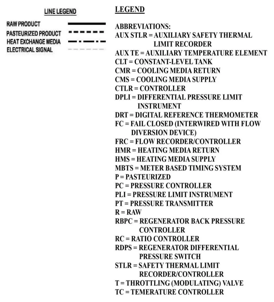
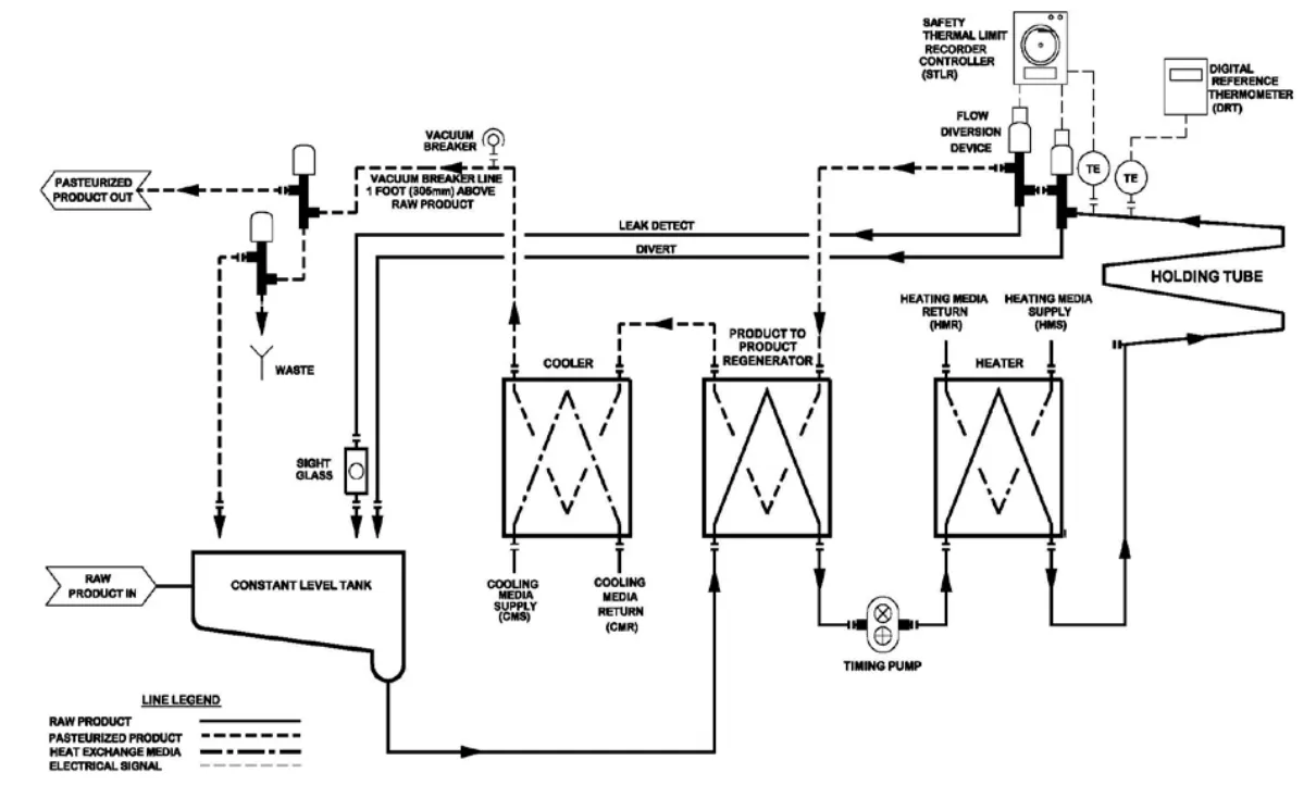
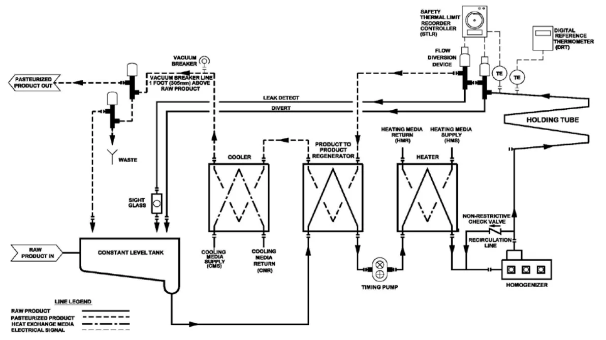
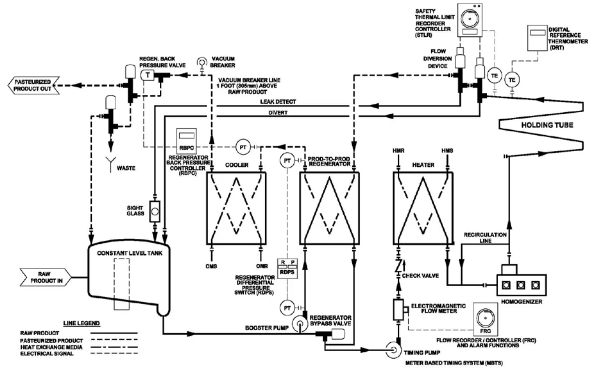
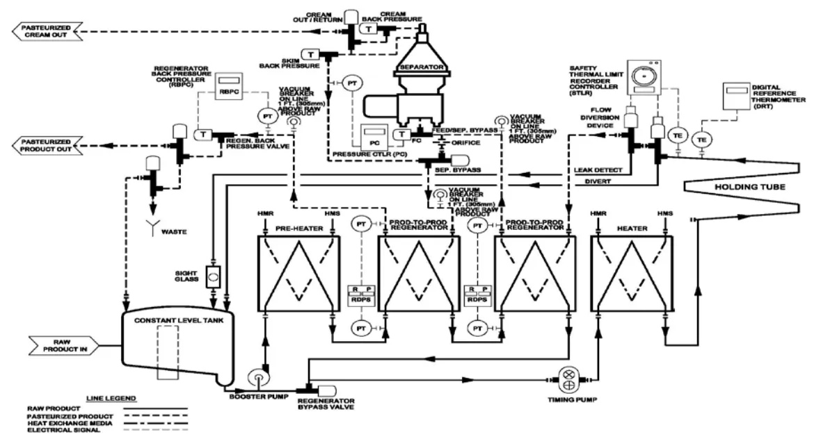
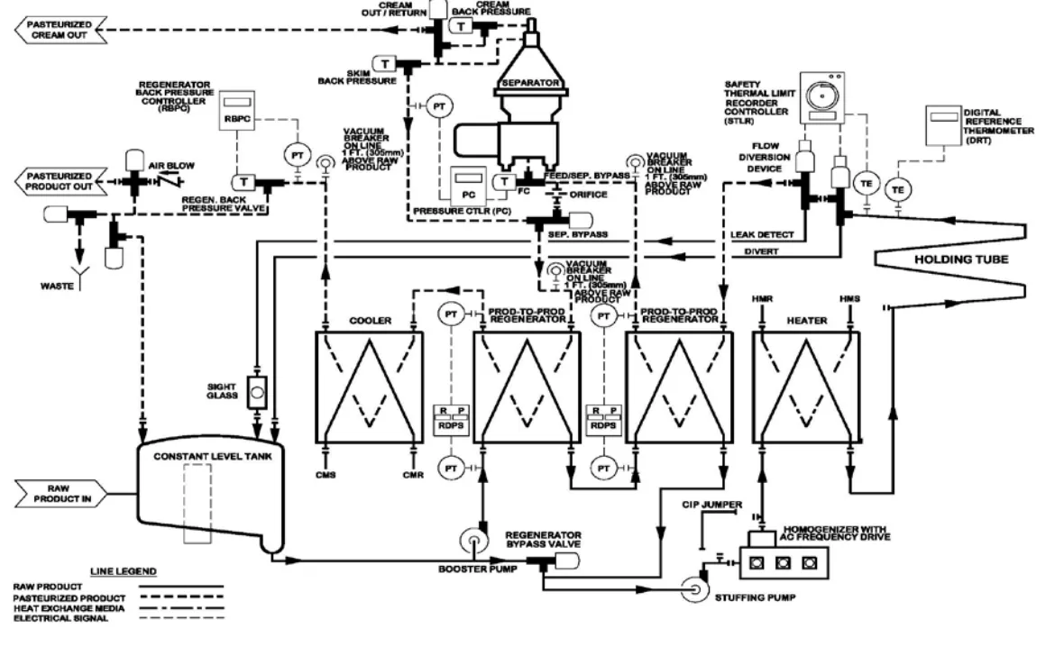
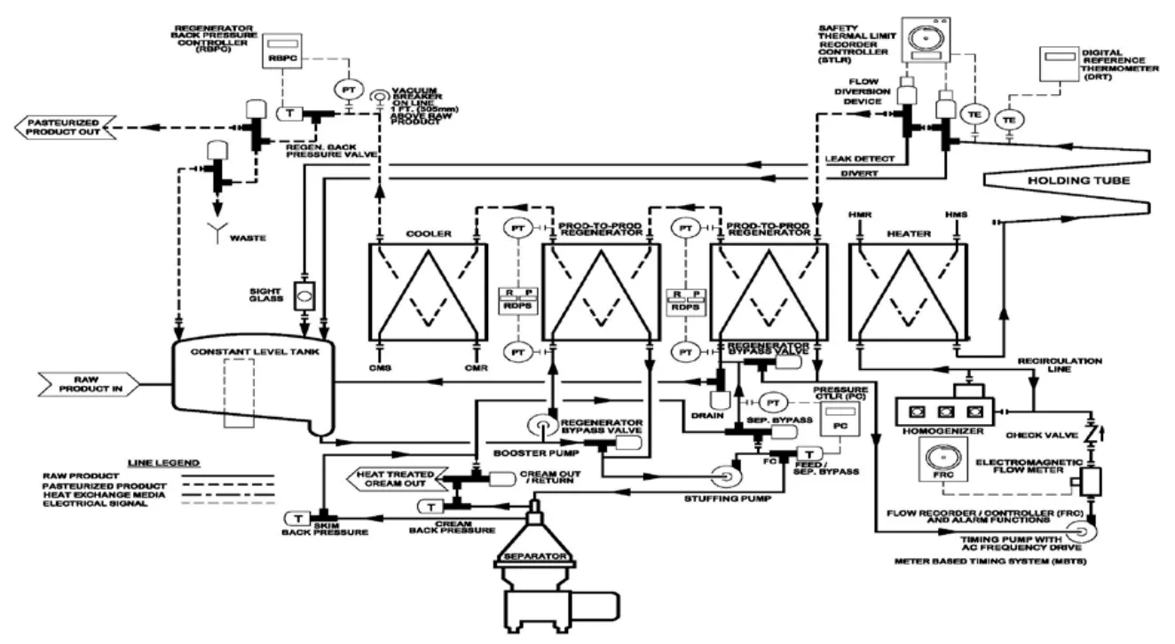
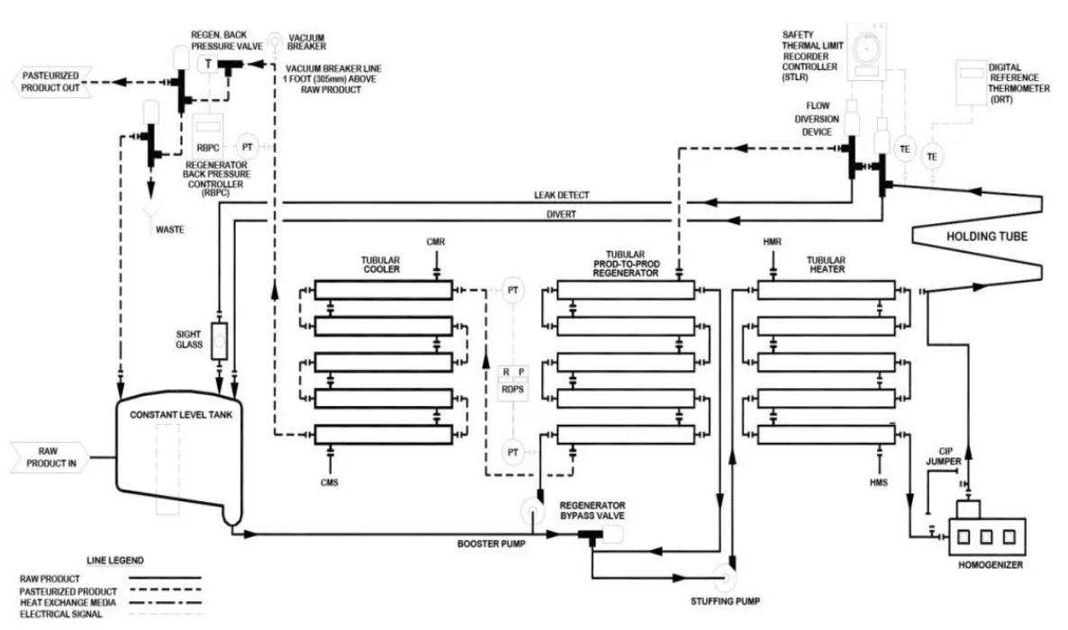
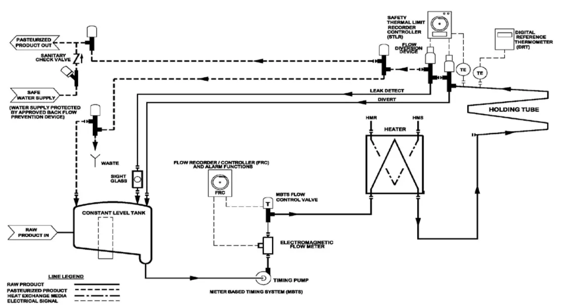
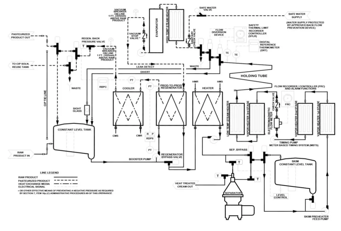
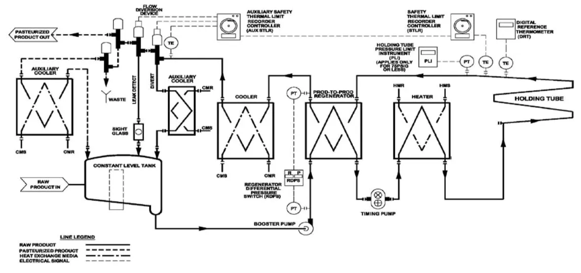
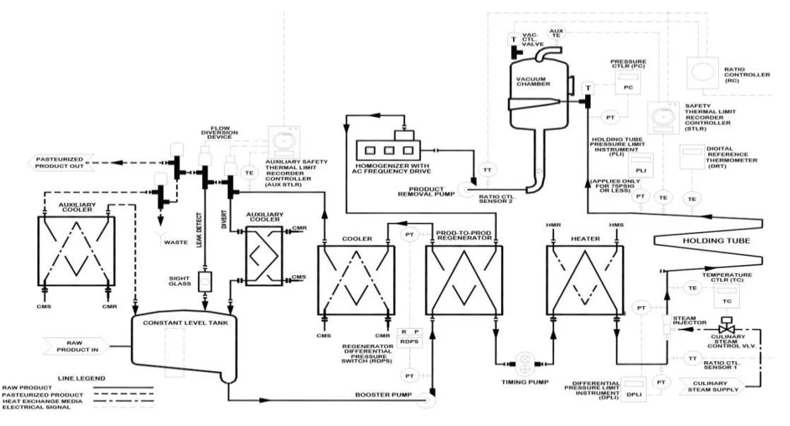
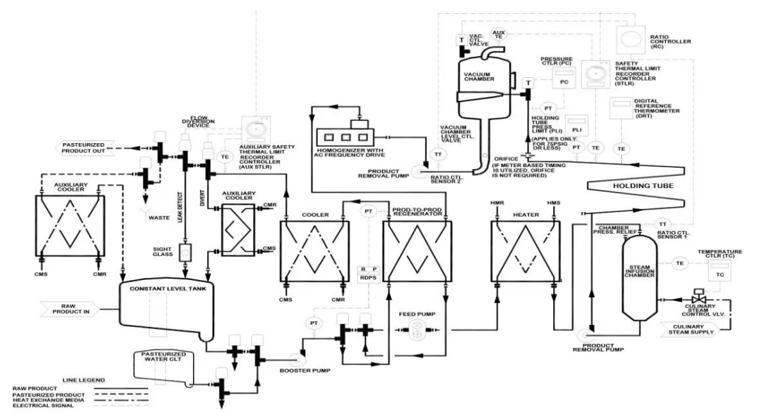
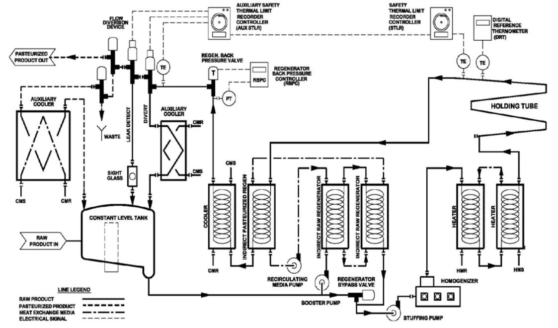
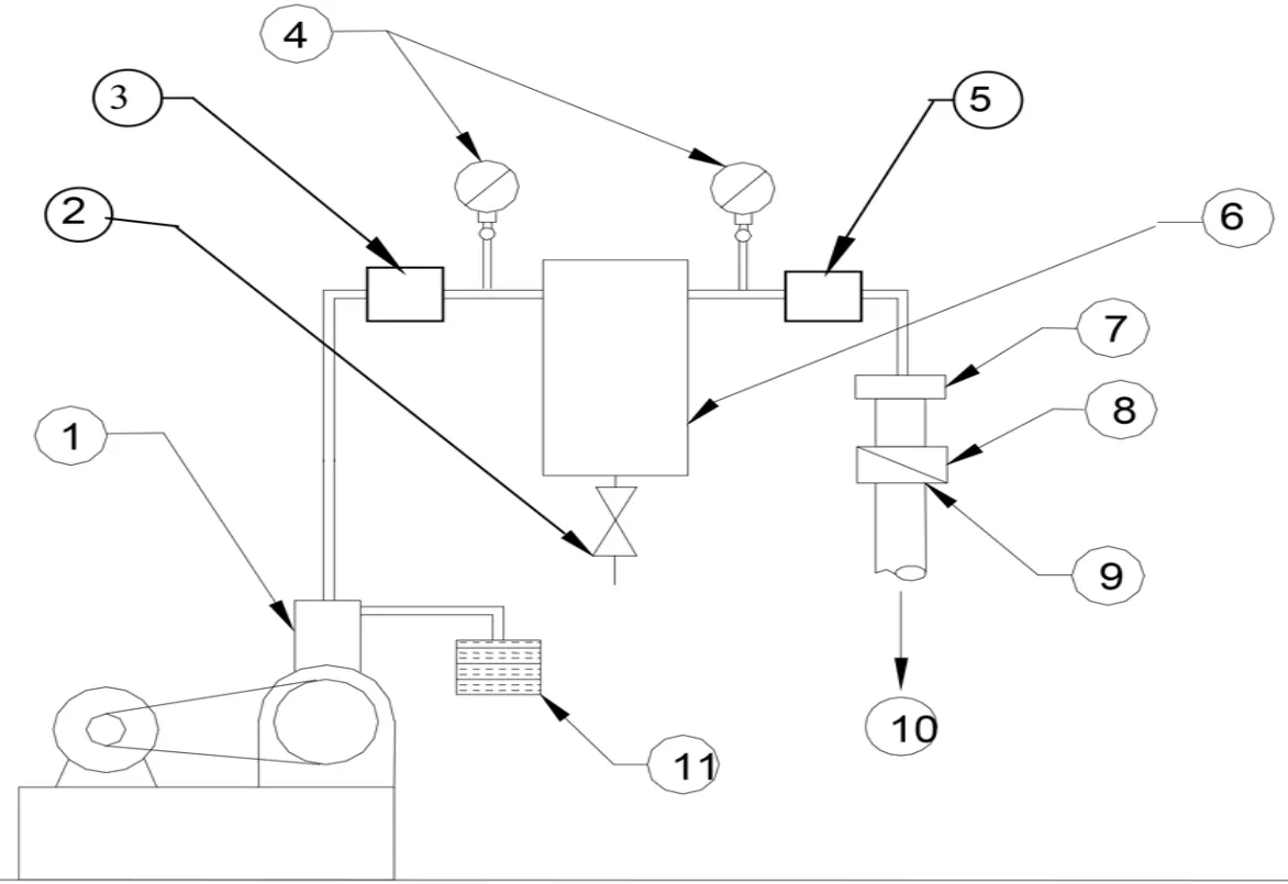
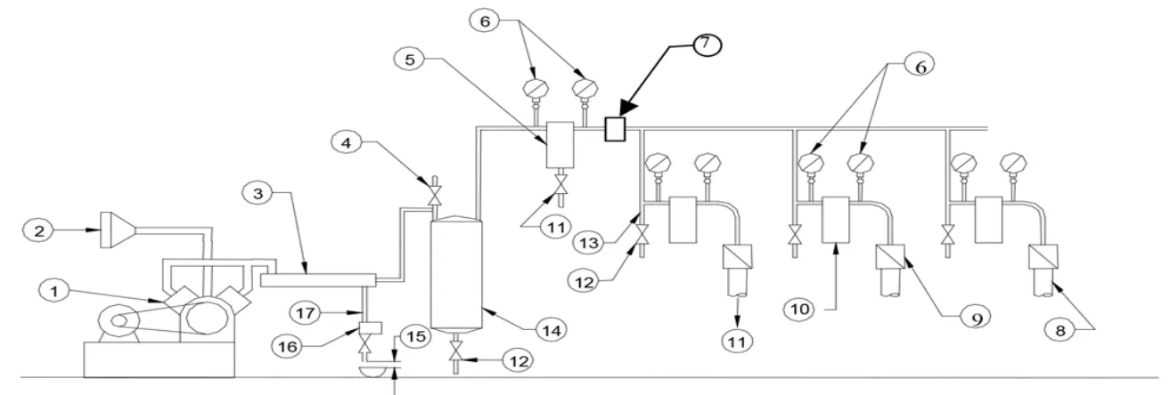
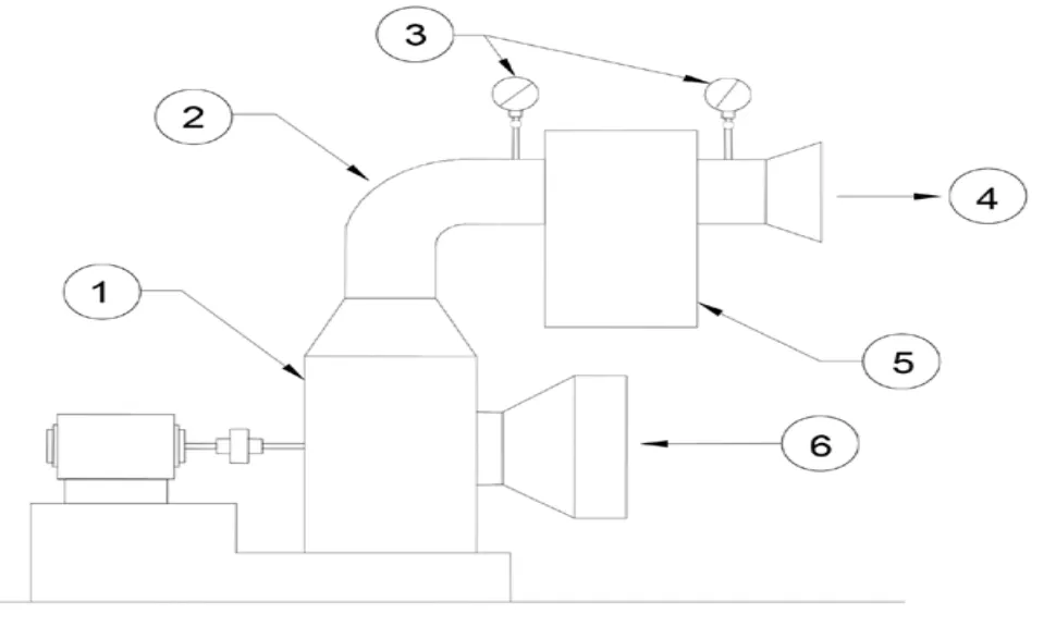
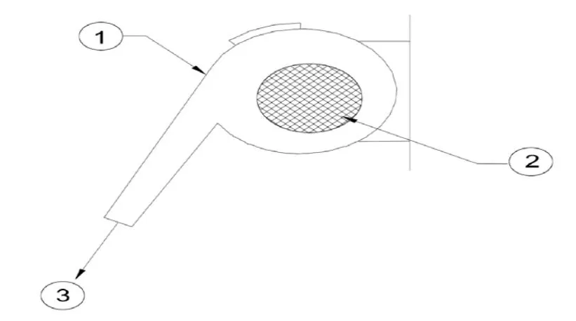
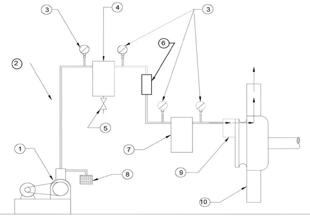
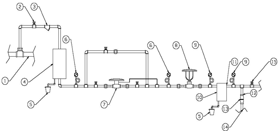
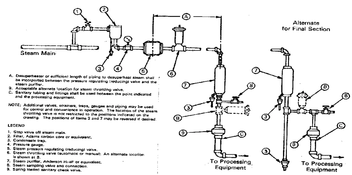
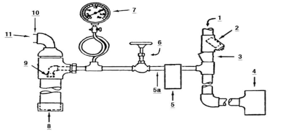
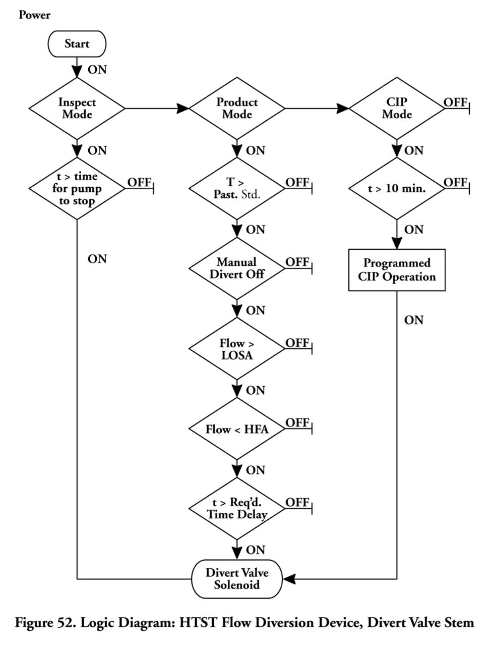
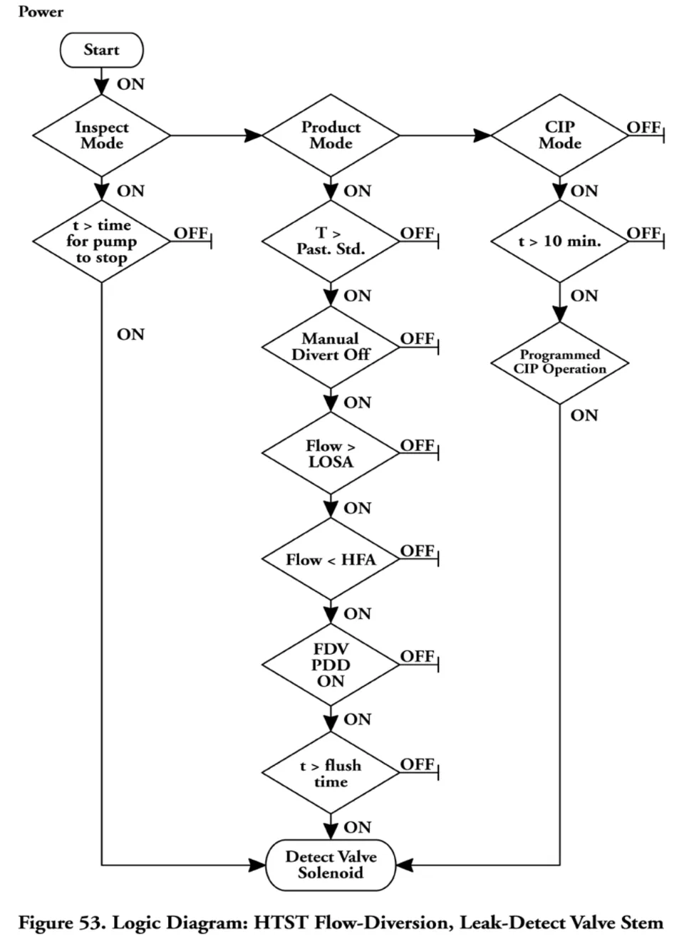
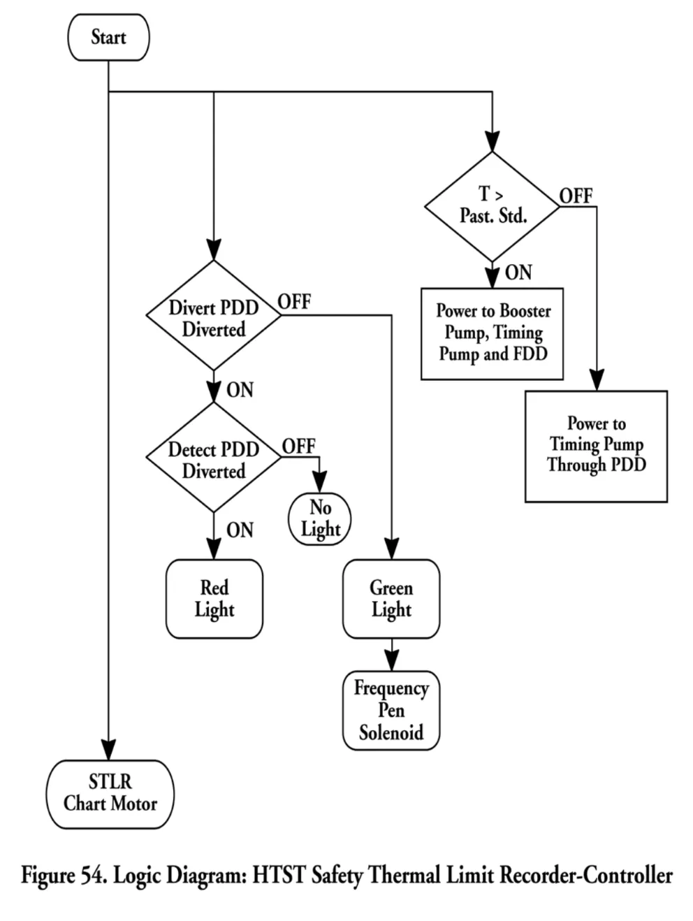
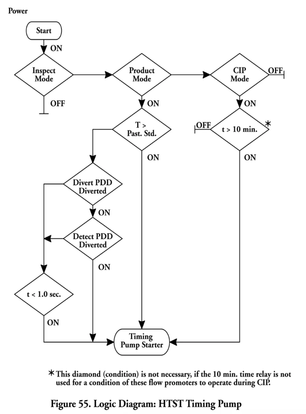
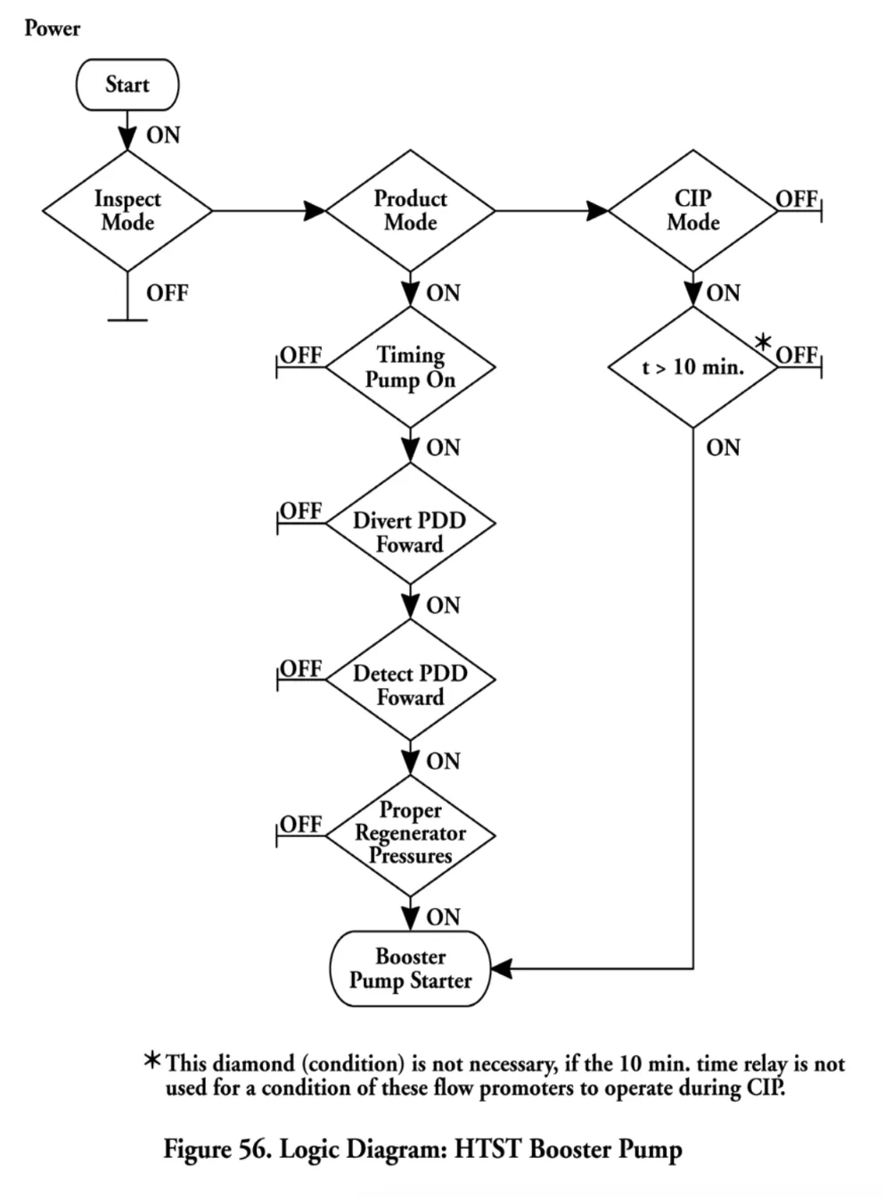
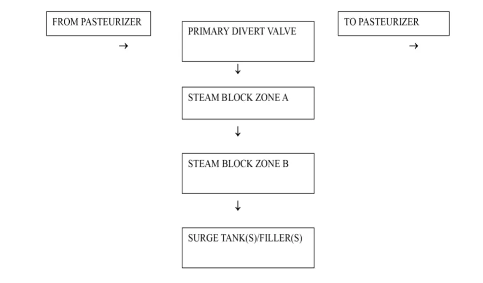
Author: G. M. Gallaspy, Jr.
Statutory Authority: Code of Ala. 1975, §22-2-2 and §22-20-7.
History: Repealed and New Rule: Filed October 18, 2018; effective December 2, 2018.