19 Va. Admin. Code § 30-70-440
Service brakes.
Effective Oct 3, 2016Virginia Register Volume 32, Issue 24§ 46.2-1165 of the Code of Virginia.Department of State Police
- A. The inspector, at a minimum, must drive all vehicles into the inspection lane and test both service and parking brakes, except vehicles the inspector is not qualified to drive. In these cases, the inspector will ride in the vehicle and observe the application of the brakes.
B. A minimum of one wheel or one wheel and drum or dust cover must be removed from each vehicle at the time of inspection except vehicles having open brake mechanisms that will permit the inspection of the brake lining, or discs and disc pads, without removing the wheel and rim.
WARNING: Failure to properly torque lug nuts may cause severe damage to the wheel.
The inspection receipt (approval and rejection) shall be marked to reflect which wheel and drum or dust cover was removed or inspected.
- C. If any braking problem is detected, the inspector may test drive or require a test drive of the vehicle.
D. Inspect for and reject if:
- 1. Any commercial motor vehicle manufactured on or after October 20, 1994, is equipped with an air brake system but is not equipped with the proper and functioning automatic brake adjuster system and brake adjuster indicator.
2. Vehicles equipped with air brakes: when the air brake adjustment on vehicles is equal to or exceeds values in the following tables for cam brakes or brake shoe travel is greater than 1/16" on wedge brakes when measured according to Illustrations #1 and #2. (See procedure in addition to illustrations.)
TABLE 1
MINIMUM CRITERIA FOR BRAKE ADJUSTMENT
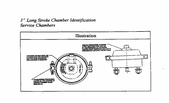
COMMERCIAL VEHICLE SAFETY ALLIANCE NORTH AMERICAN STANDARD OUT-OF-SERVICE CRITERIA Brake adjustment shall not exceed those specifications contained hereunder relating to "Brake adjustment limit." (Dimensions are in inches.)CLAMP TYPE BRAKE CHAMBER DATA Type Outside Diameter Brakes Exceeding the Maximum Brake Adjustment Limit Shall be Readjusted 6 4-1/2 (114mm) 1-1/4 (32mm) 9 5-1/4 (133mm) 1-3/8 (35mm) 12 5-11/16 (145mm) 1-3/8 (35mm) 16 6-3/8 (162mm) 1-3/4 (45mm) 20 6-25/32 (172mm) 1-3/4 (45mm) 24 7-7/32 (184mm) 1-3/4 (45mm) 30 8-3/32 (206mm) 2.0 (51mm) 36 9.0 (229mm) 2-1/4 (57mm) NOTE: A brake found at the adjustment limit is not to be rejected. LONG STROKE CLAMP TYPE BRAKE CHAMBER DATA Type Outside Diameter Brakes Exceeding the Maximum Brake Adjustment Limit Shall be Readjusted 12 5-11/16 (14.5mm) 1-3/4 (45mm) 16 6-3/8 (162mm) 2.0 (51mm) 20 6-25/32 (172mm) 2.0 (51mm) 24 7-7/32 (184mm) 2.0 (51mm) 24* 7-7/32 (184mm) 2.5 (64mm) 30 8-3/32 (206mm) 2.5 (64mm) *For 3" maximum stroke type 24 chambers NOTE: A brake found at the adjustment limit is not to be rejected. NOTE: 3" long stroke brake chambers are identified by square air line ports and a trapezoidal tag attached to the chamber. BOLT TYPE BRAKE CHAMBER DATA Type Outside Diameter Brakes Exceeding the Maximum Brake Adjustment Limit Shall be Readjusted A (12) 6-15/16 (176mm) 1-3/8 (35mm) B (24) -3/16 (234mm) 1-3/4 (45mm) C (16) 8-1/16 (205mm) 1-3/4 (45mm) D (6) 5-1/4 (133mm) 1-1/4 (32mm) E (9) 6-3/16 (157mm) 1-3/8 (35mm) F (36) 11.0 (279mm) 2-1/4 (57mm) G (30) 9-7/8 (251mm) 2.0 (51mm) NOTE: A brake found at the adjustment limit is not to be rejected. ROTOCHAMBER DATA Type Outside Diameter Brakes Exceeding the Maximum Brake Adjustment Limit Shall be Readjusted 9 4-9/32 (109mm) 1-1/2 (38mm) 12 4-13/16 (122mm) 1-1/2 (38mm) 16 5-13/32 (138mm) 2.0 (51mm) 20 5-15/16 (151mm) 2.0 (51mm) 24 6-13/32 (163mm) 2.0 (51mm) 30 7-1/16 (180mm) 2-1/4 (57mm) 36 7-5/8 (194mm) 2-3/4 (70mm) 50 8-7/8 (226mm) 3.0 (76mm) NOTE: A brake found at the adjustment limit is not to be rejected. DD-3 BRAKE CHAMBER DATA Type Outside Diameter Brakes Exceeding the Maximum Brake Adjustment Limit Shall be Readjusted 30 8-1/8 (206mm) 2-1/4 (57mm) NOTE: This chamber has three air lines and is found on motor coaches. NOTE: A brake found at the adjustment limit is not to be rejected. WEDGE BRAKE DATA The combined movement of both brake shoe lining scribe marks shall not exceed 1/8 inch (3.18mm). PROCEDURE FOR MEASURING CAM AND WEDGE BRAKES AND HOW TO PROPERLY IDENTIFY 3" LONG STROKE CHAMBERS
On vehicles equipped with cam brakes, mark each brake chamber push rod at the face of the brake chamber with the brakes released. Apply the air brakes fully, minimum air pressure of 90 to 100 psi, and measure the distance the push rod travels from the face of the chamber to the mark previously made when the brakes were released. This measurement is the push-rod stroke (see illustration).
On vehicles equipped with wedge brakes, remove the inspection hole cover at each dust shield and with the brakes released, scribe a line on the edge of the brake lining. Apply the air brakes fully and measure the distance the brake lining travels.


3. Brake hose and tubing. There is any leakage in any hydraulic, air or vacuum lines; hoses have any cracks, crimps, restrictions, or are abraded exposing fabric into second ply of fabric; tubing or connections leak, are crimped, restricted, cracked, or broken.
- a. Hose with any damage extending through the reinforcement ply. Rubber impregnated fabric cover is not a reinforcement ply. Thermoplastic nylon may have braid reinforcement or color difference between cover and inner tube. Exposure of second color is cause for rejection.
- b. Bulge or swelling when air pressure is applied.
- c. Two hoses improperly joined (such as a splice made by sliding the hose ends over a piece of tubing and clamping the hose to the tube).
d. Brake tubing and hose must:
- (1) Be long and flexible enough to accommodate without damage all normal motions of the parts to which it is attached;
- (2) Be secured against chaffing, kinking, or other mechanical damage; and
- (3) Be installed in a manner that prevents it from contacting the vehicle's exhaust system or any other source of high temperatures.
- e. Any hydraulic brake tubing has been repaired using a compression fitting.
4. Service brakes.
- a. There is less than 1/5 reserve in pedal travel of the service brake when fully applied on all hydraulic, mechanical, or power-assisted hydraulic braking systems.
b. When tested on dry, hard, approximately level road free from loose material at a speed of 20 miles per hour without leaving a 12-foot wide lane, a distance in excess of the following stopping distance is obtained:
Any bus, truck or tractor - 40 feet;
All combinations of vehicles - 40 feet.
c. Every motor vehicle, trailer or semitrailer is not equipped with operational brakes on all wheels (except as shown in subdivision D 4 c (1) of this section) or any brake has been disconnected or rendered inoperative or improperly installed.
- (1) Road tractors, tractor trucks, or trucks if manufactured prior to July 25, 1980, having three or more axles are not required to have brakes on the steering axle; however, if installed must be inspected and meet all requirements of this section.
- (2) Missing, bent or broken mechanical components including: shoes, lining pads, spring, anchor pin, spiders, cam rollers, push rods and air chamber mounting bolts, air reservoirs not securely mounted or leaks.
- (3) Absence of braking action on any axle required to have brakes, upon application of the service brakes (such as missing brakes or brake shoes, failing to move upon application of a wedge, S-cam or disc brake).
- (4) Loose brake components including air chambers, spiders and cam shaft support brackets.
- (5) Audible air leak at brake chamber (example: ruptured diaphragm, loose chamber clamp, etc.)
d. Linings or pads are broken or cracked so that brake pad is not firmly attached to the shoe or improperly installed or cracks on the friction surface extends to the open edge.
- (1) Rivets or bolts are loose or missing.
- (2) Lining or pad friction surface is saturated with oil, grease or brake fluid.
e. Nonsteering axles. Lining has a thickness less than 1/4 inch at the shoe center for air drum brakes, 1/16 inch or less at the shoe center for hydraulic and electric drum brakes and less than 1/8 inch for air disc brakes, lining with a thickness less than 3/16 inch for a shoe with a continuous strip of lining or to wear indicators if so equipped.
- (1) Steering axles. Lining has thickness less than 1/4 inch at the shoe center from drum brakes, less than 1/8 inch for air disc brakes and 1/16 inch or less for hydraulic disc and electric brakes, lining with a thickness less than 3/16 inch for a shoe with a continuous strip of lining or to wear indicators if so equipped.
(2) Mismatch across any power unit steering axle of:
- (a) Air chamber sizes.
- (b) Slack adjuster length.
- f. Thickness of riveted or bolted lining is less than 2/32 of an inch above the rivet or bolt head(s).
- g. Any lining or pad is misaligned or does not make full contact with the drum or rotor.
5. Brake Drums and Discs.
- a. Brake drums or brake discs (rotors) are worn or scored to the extent that their remachining would result in a failure to meet manufacturer's specifications.
b. Brake drums or discs with any external crack or cracks that open upon brake application.
NOTE: Do not confuse short hairline heat cracks with flexural cracks.
6. Mechanical linkage.
Any portion of the drum or rotor missing or in danger of falling away.
7. Hydraulic.
NOTE: Some motor vehicles, beginning with 1976 models, have a hydraulic power system that serves both the power assisted brakes and power assisted steering system. Some vehicles, beginning with 1985 models, have an integrated hydraulic actuation and anti-lock brake unit using only brake fluid.
8. Hydraulic System Operation.
Stop engine, then depress brake pedal several times to eliminate all pressure. Depress pedal with a light foot-force (30 pounds). While maintaining this force on the pedal, start engine and observe if pedal moves slightly when engine starts.
Reject vehicle if pedal does not move slightly as engine is started while force is on brake pedal.

9. Condition of hydraulic booster power brake system.
Inspect system for fluid level and leaks. Reject vehicle if there is insufficient fluid in the power steering pump reservoir; if there are broken, kinked or restricted fluid lines or hoses; if there is any leakage of fluid at the pump, steering gear or brake booster, or any of the lines or hoses in the system; or if belts are frayed, cracked or excessively worn.
10. Integrated hydraulic booster/anti-lock system operation.
With the ignition key in the off position, depress brake pedal a minimum of 25 times to deplete all residual stored pressure in the accumulator. Depress pedal with a light foot-force (25 lbs.). Place ignition key in the on position and allow 60 seconds for the brake warning light to go out and the electric pump to shut off.
Reject vehicle if the brake pedal does not move down slightly as the pump builds pressure or if the brake and anti-lock warning lights remain on longer than 60 seconds.

11. Condition of integrated hydraulic booster/anti-lock system with electronic pump.
With the system fully charged, inspect system for fluid level and leaks.
Reject vehicle if there is insufficient fluid in the reservoir; if there are broken, kinked or restricted fluid lines or hoses; or if there is any leakage of fluid at the pump or brake booster, or any of the lines or hoses in the system.
12. Vacuum system operation.
- a. Has insufficient vacuum reserve to permit one full brake application after engine is shut off.
b. Lacks an operative low-vacuum warning device as required.

Stop engine then depress brake pedal several times to eliminate all vacuum in the system. Depress pedal with a light foot-force (25 lbs.). While maintaining this force on the pedal, start engine and observe if pedal moves down slightly when engine starts.
Reject vehicle if pedal does not move down slightly as engine is started while force is on the brake pedal. In full vacuum-equipped vehicles, there is insufficient vacuum reserve for one full service brake application after engine is stopped.
13. Condition of vacuum booster power brake system.
- a. Visual inspection. Reject vehicle if there are collapsed, cracked, broken, badly chafed or improperly supported hoses and tubes, loose or broken hose clamps.
- b. There is any leakage in the hydraulic system. (Do not disturb the dust boot when checking for leaking wheel cylinders.)
- c. Fluid level in master cylinder is below the proper level for the particular vehicle.
- d. There is any evidence of a caliper sticking or binding.
14. Air brakes.
- a. Motor vehicle is equipped with air brakes and does not have an operating air pressure gauge.
b. Any bus, truck, road tractor and tractor truck manufactured after March 15, 1975, must have a visible low air warning device. Those manufactured on or before March 15, 1975, may have either an audible or visible low air warning device.
Low pressure warning device is missing, inoperative or does not operate at 55 psi and below or 1/2 the governor cut out pressure, whichever is less.
c. Compressed air reserve is not sufficient to make one full service brake application after engine is stopped, or with system fully charged, the reservoir pressure is lowered more than 30% by one full brake application.
Brake chamber push rods do not follow application of service brake pedal, or do not reach full released position (example: defective return spring).
- d. Any bus, truck, road tractor, or tractor truck manufactured after February 28, 1975, if equipped with a manually operated device to reduce or remove the braking effort upon its front wheels.
15. Electric brakes.
- a. Trailers show an amperage value more than 20% above or 30% below the brake manufacturer's maximum current rating for each brake.
- b. Ammeter shows no reading or indicator is not steady on application and release of brake controller.
- c. Any terminal connections are loose or dirty; wires are broken, frayed or unsupported; any single conductor or nonstranded wire or wires below size recommended by brake manufacturers are installed.
- d. Electrical trailer brakes do not apply automatically when breakaway safety switch is operated.
- e. Absence of braking action on any wheel required to have brakes.
- f. Missing or inoperative breakaway braking device; cable is frayed or broken.
16. Air compressor.
- a. Compressor drive belts are in condition of impending or probable failure.
- b. Loose compressor mounting bolts or compressor leaks.
- c. Cracked, broken or loose pulley.
- d. Tractor protection valve(s) is defective or inoperative.
- e. Air safety relief valve is defective or inoperative.
Statutory Authority
§ 46.2-1165 of the Code of Virginia.
Historical Notes
Derived from VR545-01-07 § 44, eff. May 1, 1990; amended, Virginia Register Volume 10, Issue 8, eff. February 9, 1994; Volume 15, Issue 2, eff. November 11, 1998; Volume 21, Issue 4, eff. September 22, 2004; Volume 24, Issue 8, eff. March 1, 2008; Volume 32, Issue 24, eff. October 3, 2016; Errata, 32:26 VA.R. 3588 August 22, 2016.