34 Pa. Code § 15.18
Allowable stresses.
(a) For steel. Parts of the structure shall be so proportioned that the sum of the maximum stresses in pounds per square inch does not exceed the following:
(1) Tension. Tension shall be regulated as follows:
Item Maximum Stresses
(pounds per square inch)Structural steel, net section 20,000 Butt welds, section through throat 20,000 Rivets on area based on nominal diameter 20,000 Bolts and other threaded parts, on nominal area at root of thread 20,000 (2) Compression. Compression shall be regulated as follows:
(i) For the purposes of this paragraph, symbols represent the following:
L = The unsupported length of the column.
r = The corresponding least radius of gyration of the section.
- (ii) Rolled steel, on short length or where lateral deflection is prevented, may not exceed 20,000 pounds per square inch.
(iii) On a gross section of columns, L/r does not exceed 120:
1,700 - .485 L2 /r2
if L/r exceeds 120:
1 + [(18,000 ÷ L2) ÷ 18,000r2 ]
(iv) The ratio of unbraced length to least radius of gyration L/r for compression members and for tension members other than rods shall not exceed the following:
Item Maximum Stresses
(pounds per square inch)For main compression members 120 For bracing and other secondary members in compression 200 For main tension members 240 For bracing and other secondary members in tension 300
(3) Bending. Bending shall be regulated as follows:
(i) For the purposes of this paragraph, the following designations will apply:
L = The unsupported length of the column.
b = The width of the compression flange.
- (ii) Extreme fibres of rolled shapes, and built up sections, net section, if lateral deflection is prevented, may not exceed 20,000 pounds per square inch.
(iii) Where L exceeds 15 times b, the stress in pounds per square inch in b may not exceed the following:
1 + [(20,000 ÷ L2 ) ÷ 2,000b2 ]
- (iv) The laterally unsupported length of beams and girders may not exceed 40 times b in width of the compression flange.
- (v) Extreme fibres of pins, when the forces are assumed as acting at the center of gravity of the pieces may not exceed 30,000 pounds per square inch.
(4) Shearing. Shearing shall be regulated as follows:
(i) For the purposes of this paragraph, the following designations will apply:
A = The gross area of the web in inches.
V = The total shear.
h = The height between flanges in inches.
t = The thickness of the web in inches.
(ii) The following table will apply:
Item Maximum Stresses
(pounds per square inch)Pins 15,000 Power-driven rivets 15,000 Turned bolts in reamed holes with a clearance of not more than 1/50 inch 15,000 Hand-driven rivets 10,000 Unfinished bolts 10,000 The gross area of the webs of beams and girders where h is not more than 60 times t 13,000 (iii) The gross area of the webs of beams and girders if the web is not stiffened, where h is more than 60 times t, the thickness of the web, the maximum shear per square inch, V/A may not exceed:
1 + [(18,000 ÷ h2 ) ÷ 7,200t2 ]
- (iv) A section through the throat of a fillet weld may not exceed 13,600 pounds per square inch.
(5) Bearing. Bearing shall be regulated as follows:
- (i) For the purposes of this paragraph, the letter ‘‘d’’ shall designate the diameter of the roller in inches.
(ii) The following table will apply:
Maximum Stresses
(pounds per square inch)Item Single Shear Double Shear Pins 32,000 32,000 Power-driven rivets 32,000 40,000 Turned bolts in reamed holes 32,000 40,000 Hand-driven bolts 20,000 25,000 Unfinished bolts 20,000 25,000 - (iii) On expansion rollers, pounds per linear inch, -600d.
(6) Combined stresses. Combined stresses shall conform with the following:
(i) For the purposes of this paragraph, the following designations will apply:
Fa = Axial unit stress that would be permitted by this specification if axial stress only existed.
Fb = Bending unit stress that would be permitted by this specification if bending stress only existed.
fa = Axial unit stress (actual) = axial stress divided by area of member.
fb = Bending unit stress (actual) = bending moment divided by section modulus of member.
- (ii) For stresses due to wind sway loads, combined with those due to dead or live loads, the permissible total working stress may be increased 33 1/3%, if the section thus found is not less than that required by the dead or live loads alone.
- (iii) Members subject to both axial and bending stresses shall be so proportioned that the quantity fa/Fa+fb/Fb does not exceed unity.
- (7) Members carrying wind and sway only. For members carrying wind and sway stresses only, the permissible working stresses may be increased 33 1/3%.
- (8) Welding. Welds shall be made only by operators who have qualified by the tests prescribed in the Standard Qualification Procedure of the American Welding Society to perform the type of work required, except that this provision need not apply to tack welds not later incorporated into finished welds carrying calculated stress.
(b) For wood. Allowable unit stresses for wood parts of grandstands shall be considered in light of the following:
(1) Wood parts shall be so designed and proportioned that their stresses do not exceed the allowable unit stresses in the following table:
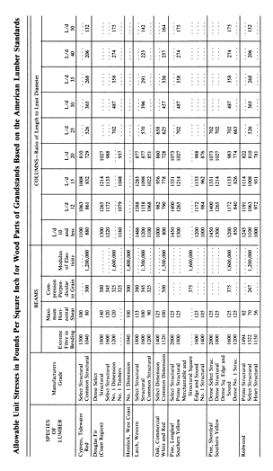
- (2) A species or grade of wood excluded from paragraph (1) may not be used except when permitted by the Department and after the wood is determined to be satisfactory.
- (3) For stresses produced by wind loads or impact only, or by a combination of wind or impact loads and dead and live loads, allowable stresses may be increased 50% if the resulting sections are not less than those for dead and live loads alone.
- (4) Connections to wooden members shall be by means of rivets, bolts, lag screws, except lag screws in tension or for field connections or approved modern timber connectors. It is recommended that a bulletin issued in the United States Department of Commerce entitled, ‘‘Modern Connection for Timber Construction’’ be consulted. The use of nails and wood screws is permissible for holding parts together, but for designing purposes the nails or screws shall be considered incapable of transmitting calculable stresses.
- (5) Nails or screws may not be used if their loosening or splitting of the surrounding wood causes stresses in excess of those permitted or would jeopardize the strength and stability of the structure or the safety of its occupants.
- (6) Connections to wooden tension members may be by means of not less than two bolts, rivets or lag screws or approved modern timber connectors. Reference should be made to the bulletin referred to in paragraph (4). Adequate provision shall be made to prevent wood splitting at such connections.
(7) The bearing values of bolts in wood shall be calculated by the following tables:
(i) Basic stresses for calculating safe loads for bolted joints shall be subject to the following:
- (A) The stresses set forth in subparagraph (i) apply to seasoned timber used in dry covered locations. Exposed parts of grandstands which may be used outdoors require 7/8 of those values.
(B) When the stress is neither parallel nor perpendicular to the grain of the wood, the maximum basic stress in pounds per square inch shall not exceed the following:
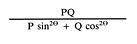
in which P is the allowable basic stress parallel with the grain, Q is the allowable basic stress perpendicular to the grain, and O is the angle between the direction of the grain and the direction of the load normal to the face considered.
Basic Stress
(pounds per square inch)Group Species of Wood Parallel with
the GrainPerpendicular
to the GrainSoftwoods (conifers) 2 Cedar, Alaska, Port Oxford and western red 1,000 200 2 Douglas fir (Rocky Mountain region) 1,000 200 2 Hemlock, western 1,000 200 2 Pine, Norway 1,000 200 3 Cypress, southern 1,300 275 3 Douglas fir (coast region) 1,300 275 3 Larch, western 1,300 275 3 Pine, southern yellow 1,300 275 3 Redwood 1,300 275 3 Tamarack 1,300 275 Hardwoods (broad-leaved species) 2 Maple (soft), red and silver 1,200 250 2 Elm, American and slippery 1,200 250 2 Gum, black, red, and tupelo 1,200 250 2 Sycamore 1,200 250 3 Ash, commercial white 1,500 400 3 Beech 1,500 400 3 Birch, sweet and yellow 1,500 400 3 Elm, rock 1,500 400 3 Hickory, true and pecan 1,500 400 3 Maple (hard), black and sugar 1,500 400 3 Oak, commercial red and white 1,500 400 (ii) The percentages of basic stress parallel with the grain for calculating safe bearing stresses under bolts shall be derived as follows:
- (A) The product of the basic stress parallel with the grain selected from the table set forth in paragraph (7)(i), and the percentage for the particular L/D ratio and species group taken from the table set forth in subparagraph (i), is the safe working stress at that ratio for joints with metal splice plates. If wood splice plates are used, each of which is 1/2 the thickness of the main timber, 80% of this product is the safe working stress.
- (B) The common bolts referred to in subparagraph (i) are those having a yield point of approximately 45,000 pounds per square inch.
- (C) The high-strength bolts referred to in subparagraph (i) are those having a yield point of approximately 125,000 pounds per square inch.
Length of Bolt in Main Percentage of Basic Stress for— Member Divided Common Bolts High-strength Bolts by its Diameter Group 1 Group 2 Group 3 Group 1 Group 2 Group 3 (L/D) Woods Woods Woods Woods Woods Woods 1.0 100.0 100.0 100.0 100.0 100.0 100.0 1.5 100.0 100.0 100.0 100.0 100.0 100.0 2.0 100.0 100.0 100.0 100.0 100.0 100.0 2.5 100.0 100.0 97.7 100.0 100.0 100.0 3.0 100.0 100.0 99.0 100.0 100.0 100.0 3.5 100.0 99.3 96.7 100.0 100.0 99.7 4.0 99.5 97.4 92.5 100.0 100.0 99.0 4.5 97.9 93.8 86.8 100.0 100.0 97.8 5.0 95.4 88.3 80.0 100.0 99.8 96.0 5.5 91.4 82.2 73.0 100.0 98.2 93.0 6.0 85.6 75.8 67.2 100.0 95.4 89.5 6.5 79.0 70.0 62.0 98.5 92.2 85.2 7.0 73.4 65.0 57.6 95.8 88.8 81.0 7.5 68.5 60.6 53.7 92.7 85.0 76.8 8.0 64.2 56.9 50.4 89.3 81.2 73.0 8.5 60.4 53.5 47.4 85.9 77.7 69.6 9.0 57.1 50.6 44.8 82.5 74.2 66.4 9.5 54.1 47.9 42.4 79.0 71.0 63.2 10.0 51.4 45.5 40.3 75.8 68.0 60.2 10.5 48.9 43.3 38.4 72.5 64.8 57.4 11.0 46.7 41.4 36.6 69.7 61.9 54.8 11.5 44.7 39.6 35.0 66.8 59.2 52.4 12.0 42.8 37.9 33.6 64.0 56.7 50.2 12.5 41.1 36.4 32.2 61.4 54.4 48.2 13.0 39.5 35.0 31.0 59.1 52.4 46.3 (iii) The percentages of basic stress perpendicular to the grain used in calculating safe bearing stresses under bolts shall be derived as shown in the following tables:
(A) The safe working stress for a given value of L/D is the product of three factors:
- (I) The basic stress perpendicular to the grain taken from the table in paragraph (7)(i).
- (II) The percentage from the table set forth in clause (A).
- (III) The factor for bolt diameter, as set forth in clause (B).
- (B) No reduction need be made when wood splice plates are used except that the safe load perpendicular to the grain should never exceed the safe load parallel to the grain for any given size and quality of bolt and timber.
- (C) The common bolts referred to in Table I are those having a yield point of approximately 45,000 pounds per square inch.
- (D) The high-strength bolts referred to in Table I are those having a yield point of approximately 125,000 pounds per square inch.
- (8) For other materials. Other materials when used shall be so designed and proportioned that their stresses do not exceed the allowable unit stresses generally accepted as safe by engineering practice.
TABLE I Percentage for Common Bolts Length ofBolt inMainMemberdivided by itsDiameter(L/D)Group 1ConifersandGroup 1HardwoodsGroup 2ConifersGroup 2HardwoodsandGroup 3ConifersGroup 3HardwoodsPercentagefor High-StrengthBolts(all groups) 1.0100.0100.0100.0100.0100.0 5.5100.0100.0100.099.0100.0 6.0100.0100.0100.096.3100.0 6.5100.0100.099.592.3100.0 7.0100.0100.097.386.9100.0 7.5100.099.193.381.2100.0 8.0100.096.188.175.0100.0 8.598.191.782.169.999.8 9.094.686.376.764.697.7 9.590.080.971.960.094.2 10.085.076.267.255.490.0 10.580.171.662.951.685.7 11.076.167.659.348.481.5 11.572.164.155.645.477.4 12.068.661.052.042.573.6 12.565.358.049.040.070.2 13.062.255.345.937.566.9
TABLE II Diameter of Bolt(in inches)Diameter Factor 1/42.50 3/81.95 1/21.68 5/81.52 3/41.41 7/81.33 11.27 1-1/41.19 1-1/21.14 1-3/41.10 21.07 2-1/21.03 3 and over1.00
Source
The provisions of this § 15.18 adopted August 15, 1933; amended through July 1, 1968.
Cross References
This section cited in 34 Pa. Code § 15.11 (relating to applicability); and 34 Pa. Code § 15.17 (relating to materials).